Difference between revisions of "DRAFT - Design Considerations for Computer Enclosures Revision"
(Created page with "'''DRAFT - Design Considerations for Computer Enclosures'''<br><br> Awaiting 2 items: (1) changes desired by Doug (2) file corrections in [http://www.protocase.com/pdf/Motherb...") |
m |
||
| Line 1: | Line 1: | ||
'''DRAFT - Design Considerations for Computer Enclosures'''<br><br> | '''DRAFT - Design Considerations for Computer Enclosures'''<br><br> | ||
| − | Awaiting 2 items: (1) changes desired by Doug (2) file corrections in [http://www.protocase.com/pdf/Motherboard_enclosure_tutorial_2D_dxf_CAD_files.zip '''DXF'''] and [http://www.protocase.com/pdf/Download_related_CAD_drawings_3D_SLDPRT.zip '''SLDPRT'''] | + | Awaiting 2 items: (1) changes desired by Doug Milburn (2) file corrections in [http://www.protocase.com/pdf/Motherboard_enclosure_tutorial_2D_dxf_CAD_files.zip '''DXF'''] and [http://www.protocase.com/pdf/Download_related_CAD_drawings_3D_SLDPRT.zip '''SLDPRT'''] |
===Introduction=== | ===Introduction=== | ||
Latest revision as of 14:42, 26 September 2016
DRAFT - Design Considerations for Computer Enclosures
Awaiting 2 items: (1) changes desired by Doug Milburn (2) file corrections in DXF and SLDPRT
Contents
Introduction
This paper covers essential considerations for computer enclosure design, whether you use Protocase Designer or another CAD program. Although the examples given are for ATX and Mini-ITX motherboards, the concepts and procedures apply to enclosures for all motherboards and custom-built circuit boards. The most common configuration is used, in which the board is mounted horizontally on the base of the enclosure and the I/O connectors are accessed through the rear of the enclosure. Key tasks are to design the mounting pattern on the base, and the openings for the I/O connector and card slot(s) on the rear panel.
Note: If you are planning to create an ATX or Mini-ITX computer enclosure with Protocase Designer, you can use Designer templates that include the motherboard layout and/or the hardware cutouts that are referenced in this paper. The templates and cutouts will save you the time and trouble of measuring dimensions for many items in the enclosure. Also, if you have a .DXF file of the PCB drawing, you can import the DXF into Designer to get the mounting hole locations and to check the fit.
Terms Used
- PCB: Printed Circuit Board, either plain or populated with components.
- Motherboard: The PCB for a computer, containing the CPU (Central Processing Unit).
- I/O: Input/Output device for computer peripherals, such as a USB (Universal Serial Bus) or a PCI (Peripheral Component Interconnect) expansion card. The enclosure design includes cutouts for connectors on the I/O.
- Connector: The part of a cable that plugs into a port or interface to connect one device to another. Connector types include DB, DIN, and Centronics.
The Design Process
Overall dimensions, mounting points (hole patterns), PCI card details, and I/O connector block areas are standardized on all ATX and Mini-ITX form factors. The drawings below show the overall dimensions and mounting points for these boards. To locate the board correctly within your enclosure, you must provide sufficient clearance between the edges of the board and the enclosure walls and other components. This includes calculating the minimum clearances between the edges of the motherboard and fans, drives, cables, and the enclosure walls; the thickness of enclosure walls; and the height of standoffs. Note: For greater detail on the drawings used in this paper, you can download them in either DXF or SLDPRT format.
Motherboard Mounting Considerations
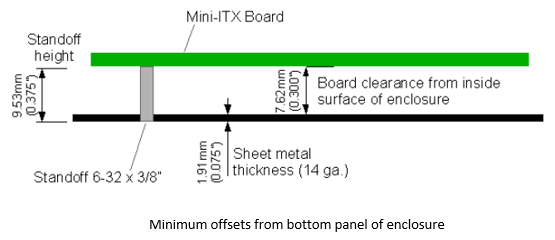
Motherboards must be attached to the enclosure with standoff fasteners, raising the board above the floor of the enclosure to avoid contact of parts on the underside with the metal casing, as shown below.
In addition, if you are making your own board, components may be mounted on both sides of the board. In either of these cases, you will need to know the distance between the board and the enclosure. Because standoffs extend through the enclosure wall, you must subtract the the thickness of the sheet metal, plus 0.010” allowance for manufacturing tolerance, from the standoff length. A 0.375" standoff mounted in a 14-gauge (0.075") enclosure wall will provide only 0.30" clearance to the surface of the board, and less if the metal is thicker. Standard motherboard mounting holes accept a 6-32 thread size, and a 3/8" standoff should be suitable for most boards. The use of PEMs is the standard method to achieve this. If you do not use 6-32 x 3/8" standoffs, take care to consider surrounding PCI card tab slots and the height of cutouts for the I/O block and PCI card cutouts.
If you are adding spacers, Protocase provides spacers (female-to-female connectors) that are designed to work with the FH-632-4ZI threaded stud or the non-zinc version. (They are included in the Protocase Designer computer enclosure templates, and with the cutouts for the ATX and Mini-ITX PEMs.) When building your own custom enclosure, you can add them to your design by using the 6-32 x 3/8" standoffs for the motherboard and adding a note that you need the spacers as well. We use a very short stud that you can screw the spacers into, so if your motherboard does not support one of the holes, you can just not put that spacer in and it will not interfere with your board. As noted earlier in this document, ensure that they are not placed too close to the sides or top of the enclosure.
Tips on optimizing your PCB design
If you are sourcing your PCB as an off-the-shelf item, then you have no control over the location of board connectors or mounting holes. Most boards are designed with mechanical mounting in mind, but if you are designing your board from scratch, make sure that mounting hardware on the board (such as PCB mounting holes and panel mount connectors) is not so close to the wall that it would interfere with the enclosure bend radius, which would make it difficult if not impossible to manufacture.
For example, below are two boards, each with two mounting holes (indicated with a red arrow) and a connector. On board (A), the mounting holes are located 0.15" from the edge of the board. The difficulty with board (A) is that it must be placed close enough to the rear panel to allow the connector to pass through it. Because the mounting holes are so close to the edge of the board, the mounting hardware (usually a PEM) will be too close to the edge of the enclosure and will interfere with the enclosure bend radius. Board (B) is done propertly; the mounting holes are far enough back from the edge of the board to prevent any interference.
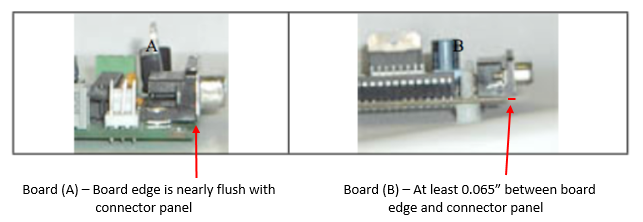
Likewise, the board edge must not be flush with any connector that is going to be mounted flush with the side of the enclosure. In the example below, the connector on board (A) is mounted so close to the edge of the board that the board will have to be mounted with its edge just touching the enclosure side. Because there is no allowance for manufacturing variability, the board could get jammed into position when it is mounted, inducing stress on the board and compromising its electrical integrity. Board (B) on the right is done properly.
A good rule of thumb is to leave at least 0.375" between the center of a mounting hole and the edge of the board. If there is less than that, contact [[mailto: info@protocase.com Protocase Engineering & Design Services]] to see if it can be manufactured. (The precise allowance depends on the size of the tool used to insert the PEM and how close to the edge the PEM is allowed. In Protocase Designer, PEMs and bends have exclusion zones displayed in red, and you will receive a warning if you place a PEM too close to a bend.)
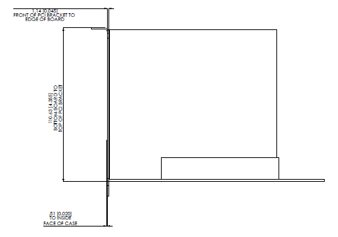
When the I/O is accessed from the lower edge of the motherboard (as it is with ATX and Mini-ITX boards), the board edge should be offset at least 0.065" from the inner face of the enclosure wall. This accommodates both the I/O plate adaptor (a small metal plate that comes with the motherboard and mounts over the I/O connectors) and the metal brackets on the PCI cards.
Allow a minimum 0.25" clearance from the other board edges to their corresponding side panels, from the board to other parts such as flanges and fasteners, and from the top of the highest component to the inside of the top of the enclosure. (If you intend to use a fan-cooled processor, see the discussion on fan clearance later in this paper.) If you use smaller clearances, be sure to investigate every possible interference, and discuss it with [[mailto: info@protocase.com Protocase Engineering & Design Services]] before submitting your design for production.
Calculating Connector Cutout Locations
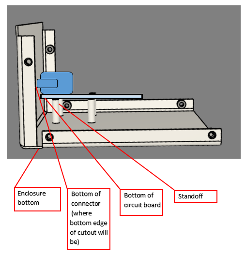
If the standoffs hold a circuit board with a connector on the rear of the enclosure, calculate the location of the bottom of the connector cutout by adding:
- the length of the standoff. Note that in this case you need not calculate the thickness of the enclosure bottom, because a 1/2" standoff is 1/2" from the outside to the top of the standoff sitting inside the box. You need to subtract the enclosure thickness only when you need to know how much free space runs under the board to the inside of the enclosure bottom.
- the height of the circuit board
- the distance from the bottom of the circuit board to the bottom of the connector
- 0.010” tolerance
Vents and Fans
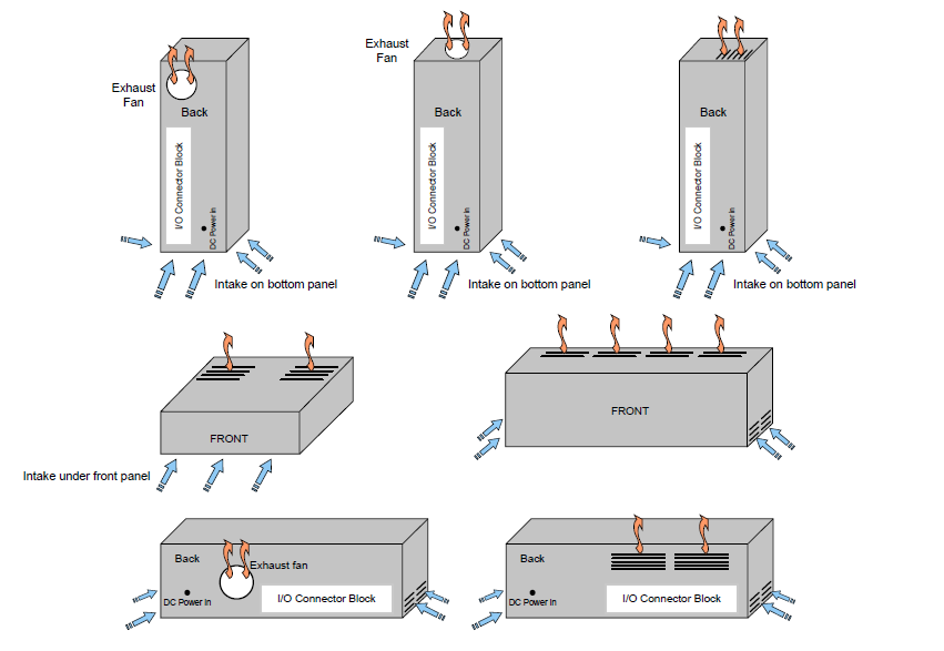
Adequate ventilation must be designed into the enclosure to avoid overheating. When designing fan and vent placement, align intake and exhaust vents to take advantage of the current that they create. It is best to arrange the vent cutouts so that air will flow across the top of the board on its way through your enclosure. The figure below shows suggested placement of ventilation cutouts and enclosure exhaust fans in an ITX enclosure.
Vent fans are rated by the number of cubic feet of cooling air they move per minute (CFM), and it's important to buy a large enough fan for your enclosure. The required CFM can be calculated as follows:
- CFM = 3.16 x Max Heat / T
- Where:
- CFM (Cubic Feet per Minute) is the volume, and is the rating by which fans are purchased;
- Max Heat is the maximum sustained power dissipation (in watts) of boards and components inside the enclosure;
- T is the maximum allowable temperature rise (in degrees Fahrenheit).
- Where:
To maximize the effect of ventilation airflow, make sure that the only openings in your enclosure are those that will be filled by switches, connectors, or panel display features. Extraneous holes in the enclosure panels can cause disruption of natural convection currents, resulting in less effective cooling of the processors. If you intend to use a fan-cooled processor with very little clearance between the fan and the enclosure wall, use fans that pull air directionally across the processor heat sink, rather than down onto the top of the sink.
Designs with air intake cutouts in the bottom panel should include feet to raise the enclosure off of its support surface. If you have bottom panel cutouts, place them outside the perimeter of the motherboard, since cutouts placed directly beneath the motherboard can allow objects to accidentally poke up through the spaces and contact the board, causing unwanted damage.
PCI Cards and Tab Slots
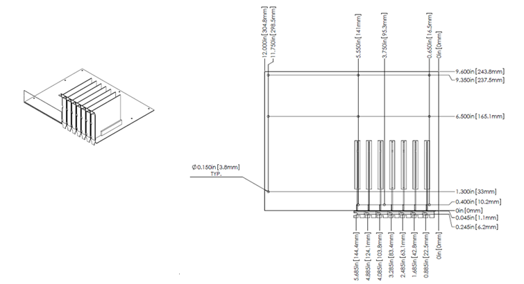
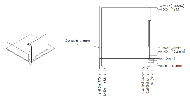
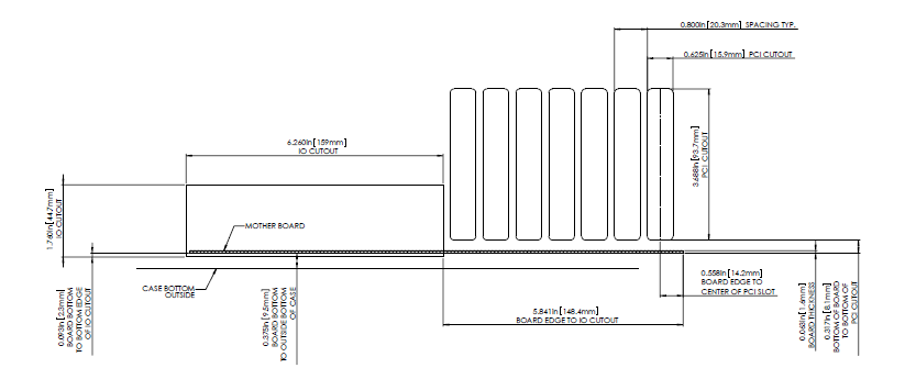
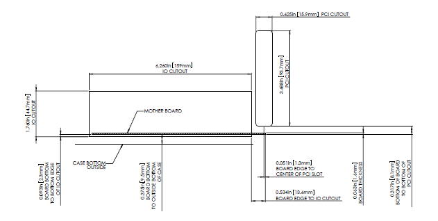
The diagrams below detail the standard slot-style cutouts for PCI card access for ATX and Mini-ITX boards. Add a flange on the top edge of the rear panel to allow the PCI card bracket(s) to be fastened. Screw holes should be placed at the dimensions shown for the screw opening on the top of the PCI card brackets. Draw the holes with a diameter of 0.1065" and add a note to “tap with 6-32 thread” because there is insufficient space to use a PEM nut here. You may also wish to add a vertical flange to the cover, to hide the gap between the cover and the flange with the screws. (In the Protocase Designer templates, both flanges are included.)
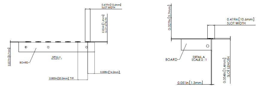
When designing the enclosure base, be sure to accommodate the tabs found on the bottom of PCI card brackets. These tabs are designed to fit into a slot in the base to help secure the card. The following drawings show the ATX (left) and Mini-ITX (right) enclosure bases, with the PCI Card slot detail for 3/8" standoffs. This slot design applies if you are using the recommended 3/8"-high standoffs, but can be avoided by using standoffs that are 7/16" or longer. If you decide to use shorter standoffs, larger clearances will be required to prevent the ends of the brackets protruding below the base of the enclosure.
If you are not anticipating using all the slots, you can either omit cutouts as required, or specify "knockouts" in which Protocase cuts almost all the way around the perimeters of the cutouts, but leaves several tiny metal bridges that keep the center in place until you decide to physically remove them. Use caution with knockouts if using cold rolled steel in damp or corrosive environments, as small patches of bare metal will be left once the centers are removed.
Related Topics
- The [Form Factors website] is a definitive source of information on motherboards.
- Protocase's [Template Generator] helps you create a design in the CAD format of your choice.
- Tutorial on Adding self-clinching fasteners to an enclosure
- Tutorial on Creating a custom cutout for a connector
- Paper on Using L-Shape Enclosures for PCBs with Opposing Connectors
- If you are importing a DXF of the circuit board, see Importing DXF files for important constraints.
- Download free CAD drawings of ATX and Mini ITX enclosures in [DXF] or ((insert link after it is fixed)) '''SLDPRT''' format.
- Linus Sebastian, creator of LinusTech on YouTube, showcases the assembly process for the components that went inside his latest custom Rackmount build.
- Looking for ideas and tips on designing a small computer case? Check out this extra small computer enclosure project from Lukasz Dyjakon. His case is designed so that the two hottest components in the case, the CPU and graphics cards, are separated and have access to fresh air directly from outside the case.
