Quick Start
This Quick Start guide walks you through the installation of Protocase Designer and its tools for creating, customizing, and quoting/ordering a design. Before beginning, you may want to review the overview of Designer features and the Glossary.
Installing Protocase Designer
The installation process is the same for both first-time installations and upgrades.
- Before installing, ensure that your graphics card drivers are compatible with Opengl 1.2+ (such as ATI and NVIDIA) and that they are up to date.
- Close all versions of Protocase Designer before installing a new one. (If you are using Windows, when you try to install Designer while another copy is running, an error occurs and the installer exits.)
- On the [Download page], click the button for the appropriate download format. The download will begin.
- Open the Protocase Designer installer file in your Downloads folder.
- If you have previously installed Designer as the Administrator (or if your anti-virus software requires that you confirm that the file is safe), right-click the installer file in Windows Explorer and choose Run as administrator. (You might have to first choose Show in folder in Google Chrome, or Open containing folder in Firefox.)
- Follow the prompts to install.
- For first-time installations, after launching Designer, you are prompted to register. Be sure to do so, so that you can receive estimates, place an order, and access the online Cutout Library.
- If your company uses a network configured such that your computer accesses the Internet through a proxy server, configure Designer to use the proxy settings:
- In Designer, choose Edit > Preferences. The Preferences dialog opens.
- Under Proxy Settings, select the Use Proxy for http checkbox, then enter the proxy address and port number (supplied by your network administrator).
- Click OK to save the settings and close the Preferences dialog.

- See Also:
Installing Protocase Designer Without Administrator Privileges
If you have no administrator access on your computer, you can still install Protocase Designer just for your user.
When you install the software, it will install to Users\<username>\Protocase Designer 4\ folder. If you have already had Protocase Designer installed as an administrator, then double-clicking a Protocase Designer file on your computer will open with the old version.
You can override this by right-clicking on the Protocase Designer file and selecting Open With. Find the newly installed version that is in your Users\<username\Protocase Designer 4\ folder.
Installation on Mac OSX
Protocase Designer requires you to have your security set to allow identified developers. This does not make your mac insecure as it still requires a properly signed application, signed with a key purchased from Apple (see https://support.apple.com/en-ca/HT202491 ).
To check your security, go to Apple menu > System Preferences… > Security & Privacy > General tab under the header "Allow applications downloaded from:"

Installation on Linux
- download linux tar file
- install openjdk8
- tar xf filename (replace with what the linux download is)
- cd jdesigner
- sudo bash ./install.sh
- follow prompts
- run $PREFIX/bin/ProtocaseDesigner.sh (default: /usr/local/bin/ProtocaseDesigner.sh)
Creating your enclosure
To begin designing your enclosure, select a template such as Consolet, Bracket, Panel, L shape, Rackmount, or U shape.
You then customize various parameters including size, thickness, material, and color. A 3D model of your enclosure is then created, which you can customize further.
- Launch Protocase Designer.
- In the Pick an Option to Start dialog box, click New File.
- Select an enclosure category and then select an enclosure type.
- Modify the enclosure parameters including size, thickness, material, and color to meet your design requirements.(For details, see Changing assembly properties.)
- Click OK to view the 3D model.


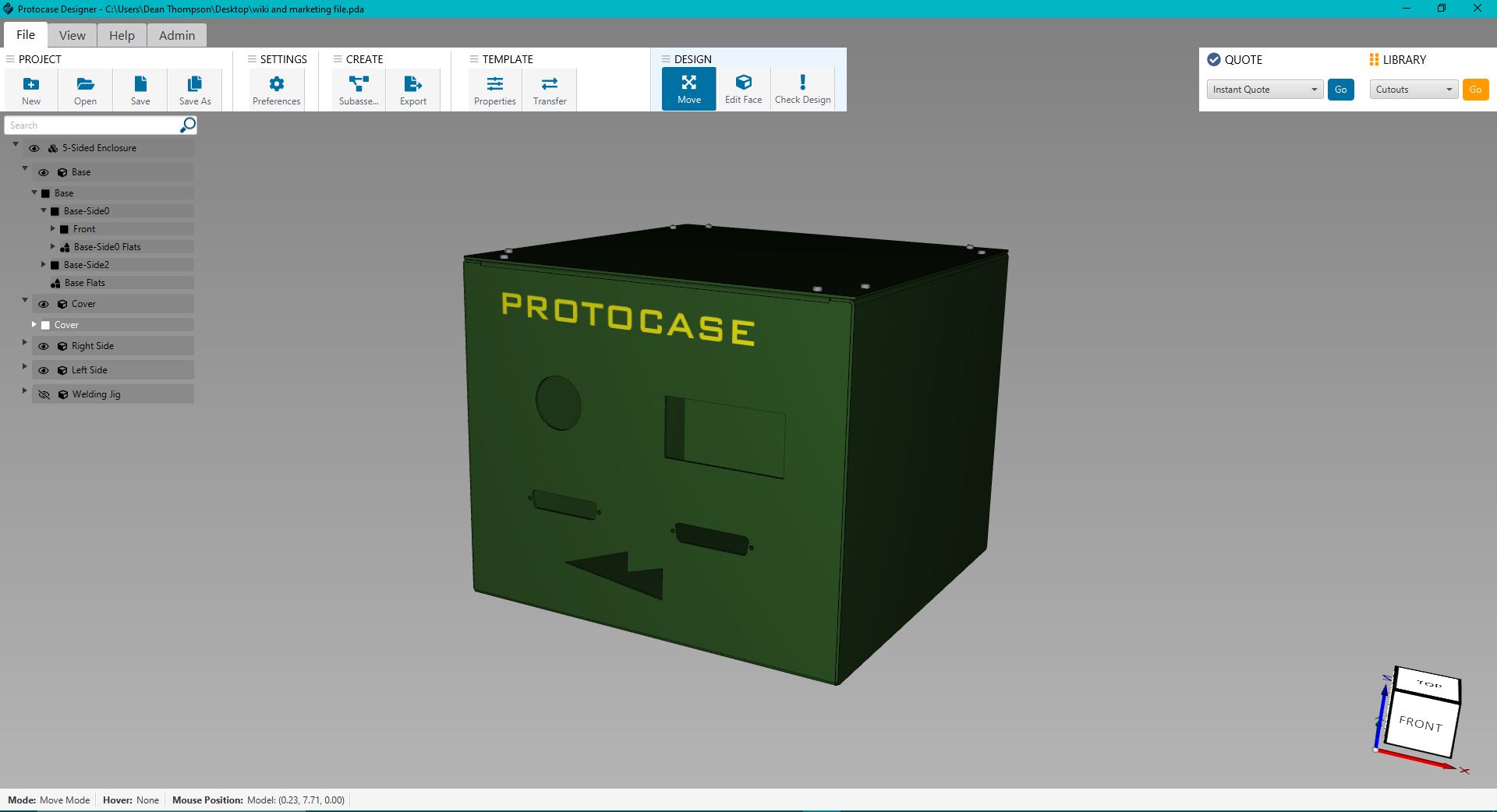
Customizing your enclosure
To customize the faces of your enclosure, you use the Face Editor, which provides many standard editing tools for creating cutouts, graphics, exclusion zones, and construction lines.
Note: If you like to use a different unit of measure or have other preferences when using Designer, you can set global options in the Preferences dialog box.
Add basic cutouts
- In the 3D View, drag the model to rotate it until it shows the face you want to edit.
- Click the Edit Face button
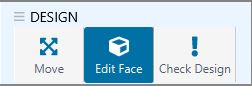 .
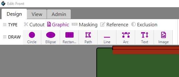
. - Click the face to edit. The Face Editor opens:
- Click a tool in the 2D Mode toolbar, and draw shapes on the face to create cutouts.
- Click Accept and Close in the 2D Standard toolbar. You can then see these cutouts applied to your 3D model.


_-_Save_Changes_-_Customizing_your_enclosure.JPG)
Add built-in cutouts
Protocase Designer offers a variety of built-in cutouts that you can add to your enclosure.
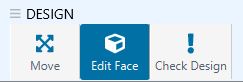
- Click the Edit Face button
 and then click a face to edit.
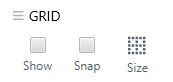
 - Click the Grid button to show the grid. Select "grid snap" to toggle grid snapping.
- On the Library menu, point to a category and then click a cutout item.
- Click on the face to place the built-in cutout.


_-_Grid_-_Built_In_Cutouts.JPG)
_-_Library_Menu_-_Built_In_Cutouts.JPG)
_-_Library_Menu_-_Built_In_Cutouts.JPG)

Add custom cutouts
You can create your own custom cutouts using the Path tool.
- Click the Path button
 in the 2D Mode toolbar.
 - Click the face to place points of the path. To finish and close the path, click the first point again.
- Click Save
 to view your enclosure in the 3D View.


Note: You can quickly create complex cutouts by merging and/or trimming objects. See Using the Trim and Merge tools to create cutouts for details.
Add hardware
You can easily place hardware on your enclosure to accommodate various components, such as self-clinching fasteners (PEMs) to mount a PCB or handles.
- Click Edit Face
 and click a face to edit.
 - Click Toggle Grid
 to show the grid. Select "grid snap" to toggle grid snapping.
 - Choose Library > Open Library.
- Choose the self-clinching fastener and its options. Note: Parts displayed with a strikeout through the name are incompatible with the enclosure's current material type and/or thickness, and cannot be selected.
- Click Place PEM and click the face to add the fasteners.
- Continue adding fasteners. Click <Escape> when you are done.
- Click Accept and Close
 .
. - Notice the full list of parts in your design on the left-hand side.
- Click the eye symbol on the faces of your design that you want to hide from the display, such as Cover Right Side Left Side.
- Rotate the model to view the fasteners.


Note: You can also create custom brackets and add them to your enclosure. See Creating and adding brackets for details.
Add text
You can add text for labeling items on your enclosure.
- Click Edit Face and click a face to edit.
- In TYPE, Click the Graphic tab.
- Click the Text tool.
- Click on the face and start typing to add text. You can change font, color and size on the right hand panel.
- Click Save .
- The text is shown in the 3D model.

.JPG)

Note: You can specify the text to be produced with silkscreening or digital printing, or you can add a note to ask Protocase to use dot peening, which is a permanent marking process that does not use ink.
Adding an image
You can add graphics such as logos to your enclosure, using silkscreen or digital printing. See Adding silkscreening or direct digital printing for details on which printing method to choose.
- Click Edit Face and click the face to edit.
- In TYPE, Click the Graphic tab.
- Click the Image tool
 .
. - In the Open dialog that is displayed, select an image file and click Open.
- Use your cursor to place your image on the face.
- Click Accept and Close to view the 3D image.
Quoting and ordering your enclosure
Once your design is complete you can instantly receive a quote and order your enclosure online.
- In the right top corner, select Instant Quote from the Quote drop-down menu.
- Protocase Designer will launch My Account. In order to quote and order in Protocase Designer, you must sign in to My Account. You can register for my account here[1]
- Once you have signed in to My Account, your Protocase Designer quote will display.
- You can update your quantity, or change your service level to Priority or Economy. Click Update to get an updated quote.

