Difference between revisions of "Quick Start"
m (→Add basic cutouts) |
m |
||
| Line 46: | Line 46: | ||
Protocase Designer offers a variety of built-in cutouts that you can add to your enclosure. | Protocase Designer offers a variety of built-in cutouts that you can add to your enclosure. | ||
#Click '''Edit Face''' [[File:button-editface.png|40px|bottom]] on the toolbar and click a face to edit. | #Click '''Edit Face''' [[File:button-editface.png|40px|bottom]] on the toolbar and click a face to edit. | ||
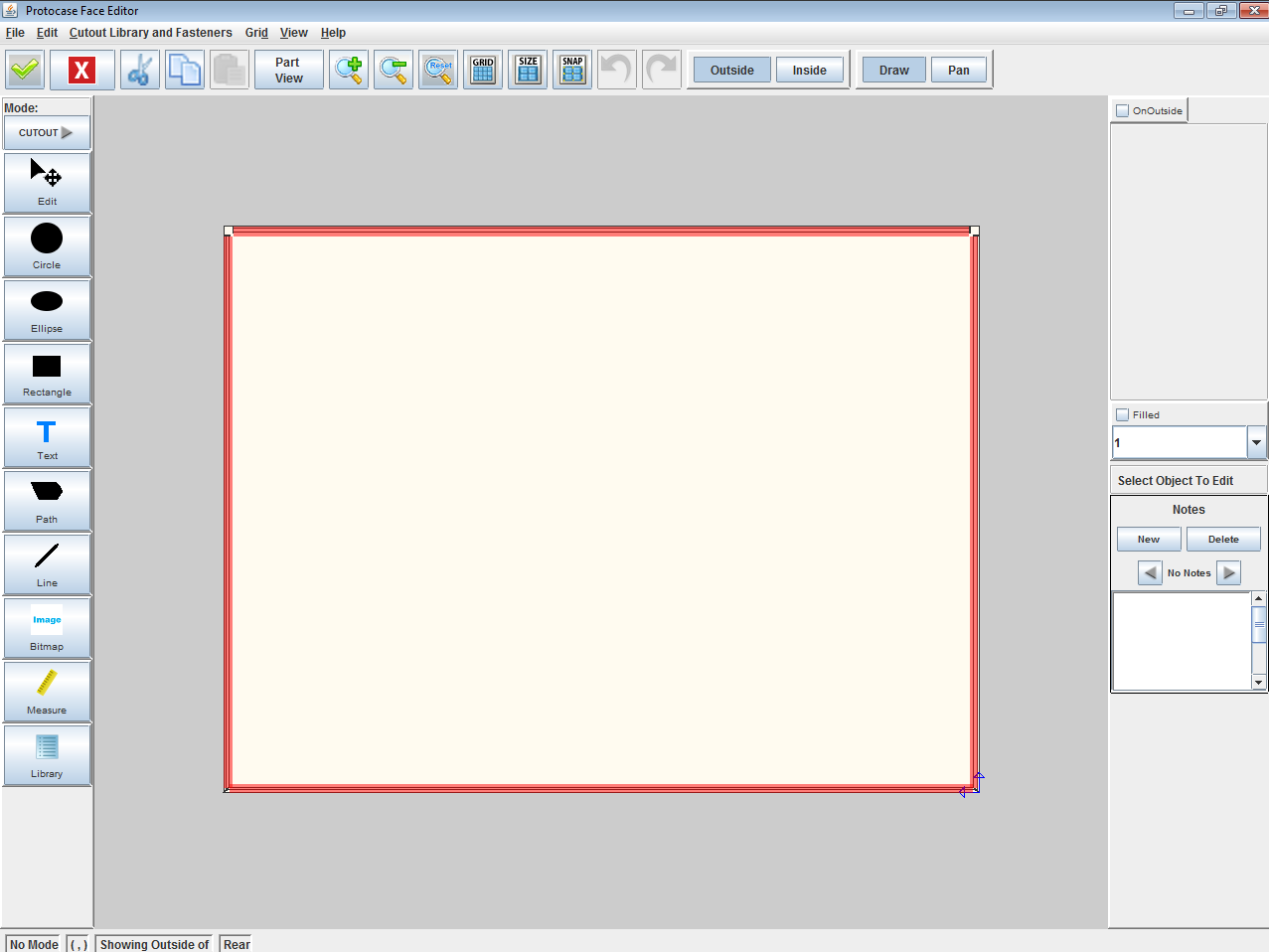
| − | #Click '''Toggle Grid''' [[File:button-togglegrid.png|35px|bottom]] on the toolbar to show | + | #Click '''Toggle Grid''' [[File:button-togglegrid.png|35px|bottom]] on the toolbar to show and snap to the grid. |
| − | # | + | #;[[File:window-faceeditor-ushape-cutout-grid.png|600px]] |
| − | #On the Cutout Library and Fasteners menu, point to a category and then click a cutout item. | + | #On the '''Cutout Library and Fasteners''' menu, point to a category and then click a cutout item. |
| − | # | + | #;[[File:window-faceeditor-DB9menu.png|600px]] |
#Click on the face to place the built-in cutout. | #Click on the face to place the built-in cutout. | ||
| − | # | + | #;[[File:window-faceeditor-ushape-db9.png|600px]] |
==Add custom cutouts== | ==Add custom cutouts== | ||
| − | You can | + | You can create your own custom cutouts using the Path tool. |
#Select the '''Path''' tool [[file:tool-path.png|40px|bottom]] on the Drawing toolbar. | #Select the '''Path''' tool [[file:tool-path.png|40px|bottom]] on the Drawing toolbar. | ||
#Click the face to place points of the path. Click the first point again to finish the path. | #Click the face to place points of the path. Click the first point again to finish the path. | ||
#:[[File:window-faceeditor-ushape-path.png|600px]]<br> | #:[[File:window-faceeditor-ushape-path.png|600px]]<br> | ||
| − | #Click '''Accept and Close''' [[File:button-acceptclose.png|40px|bottom]] | + | #Click '''Accept and Close''' [[File:button-acceptclose.png|40px|bottom]] to view your enclosure in the 3D View. |
| − | # | + | #;[[File:window-main-ushape-cutout-path.png|600px]]<br> |
| − | '''Note:''' You can quickly create complex cutouts by merging and/or trimming objects. See [[Face Editor#Path_editing:_Using_the_Trim_and_Merge_tools_to_create_cutouts|'''Using the Trim and Merge tools to create cutouts''']] for details. | + | '''Note:''' You can quickly create complex cutouts by merging and/or trimming objects. See [[Face Editor#Path_editing:_Using_the_Trim_and_Merge_tools_to_create_cutouts |'''Using the Trim and Merge tools to create cutouts''']] for details. |
==Add hardware== | ==Add hardware== | ||
You can easily place hardware on your enclosure to accommodate various components, such as self-clinching fasteners (PEMs) to mount a PCB or handles. | You can easily place hardware on your enclosure to accommodate various components, such as self-clinching fasteners (PEMs) to mount a PCB or handles. | ||
| − | #Click '''Edit Face''' [[File:button-editface.png|40px|bottom]] | + | #Click '''Edit Face''' [[File:button-editface.png|40px|bottom]] and click a face to edit. |
| − | #Click '''Toggle Grid''' [[File:button-togglegrid.png|35px|bottom]] | + | #Click '''Toggle Grid''' [[File:button-togglegrid.png|35px|bottom]] to show and snap to the grid. |
| − | # | + | #Choose '''Cutout Library and Fasteners''' > '''Place Self Clinching Fasteners'''. |
| − | # | + | #Choose the self-clinching fastener and its options. |
| − | # | + | #;[[File:dialogbox-pem.png]] |
#Click '''Place PEM''' and click the face to add the fasteners. | #Click '''Place PEM''' and click the face to add the fasteners. | ||
#Continue adding fasteners and select the '''Edit''' tool [[File:tool-edit.png|40px|bottom]] when you are done. | #Continue adding fasteners and select the '''Edit''' tool [[File:tool-edit.png|40px|bottom]] when you are done. | ||
| − | # | + | #;[[File:window-faceeditor-pem.png|600px]]<br> |
#Click '''Accept and Close''' [[File:button-acceptclose.png|40px|bottom]]. | #Click '''Accept and Close''' [[File:button-acceptclose.png|40px|bottom]]. | ||
#Choose '''Show/Hide Parts''' from the View menu. | #Choose '''Show/Hide Parts''' from the View menu. | ||
| − | # | + | #;[[File:dialogbox-showparts.png|Show/Hide Parts Dialog Box]] |
#Click to clear the '''Cover''' check box. | #Click to clear the '''Cover''' check box. | ||
#Rotate the model to view the fasteners. | #Rotate the model to view the fasteners. | ||
| − | # | + | #;[[File:window-main-pem.png|600px]] |
'''Note:''' You can also create custom brackets and add them to your enclosure. See [[Face Editor#Creating_and_adding_brackets|'''Creating and adding brackets''']] for details. | '''Note:''' You can also create custom brackets and add them to your enclosure. See [[Face Editor#Creating_and_adding_brackets|'''Creating and adding brackets''']] for details. | ||
| Line 85: | Line 85: | ||
#Click the '''Text''' tool [[File:tool-text.png|40px|bottom]]on the Drawing toolbar. | #Click the '''Text''' tool [[File:tool-text.png|40px|bottom]]on the Drawing toolbar. | ||
#Click on the face and start typing to add text. | #Click on the face and start typing to add text. | ||
| − | # | + | #;[[File:window-faceeditor-text.png|600px]] |
#Click '''Accept and Close''' [[File:button-acceptclose.png|40px|bottom]]. | #Click '''Accept and Close''' [[File:button-acceptclose.png|40px|bottom]]. | ||
| − | # | + | #;The text is shown in the 3D model. |
| − | # | + | #;[[File:window-main-text.png|600px]]<br> |
'''Note:''' For images with multiple or gradient colors, specify [[Face_Editor#Adding_silkscreening_or_direct_digital_printing|'''direct digital printing''']] instead of silkscreening. Or, you can add a note to ask Protocase to use '''[http://www.protocase.com/products/mcf_dotpeening.php dot peening]''', which is a permanent marking process that does not use ink. | '''Note:''' For images with multiple or gradient colors, specify [[Face_Editor#Adding_silkscreening_or_direct_digital_printing|'''direct digital printing''']] instead of silkscreening. Or, you can add a note to ask Protocase to use '''[http://www.protocase.com/products/mcf_dotpeening.php dot peening]''', which is a permanent marking process that does not use ink. | ||
| − | == | + | ==Adding an image== |
| − | You can add | + | You can add graphics such as logos to your enclosure, using silkscreen or digital printing. See [[Face Editor#Adding silkscreening or direct digital printing|Adding silkscreening or direct digital printing]] for details. |
#Click '''Edit Face''' [[File:button-editface.png|40px|bottom]] and click the face to edit. | #Click '''Edit Face''' [[File:button-editface.png|40px|bottom]] and click the face to edit. | ||
#Click the '''Bitmap''' tool [[File:tool-image.png|40px|bottom]] on the Drawing toolbar, then click on the face where you want to place the image. | #Click the '''Bitmap''' tool [[File:tool-image.png|40px|bottom]] on the Drawing toolbar, then click on the face where you want to place the image. | ||
| − | #In the Open dialog that is displayed, select an image file | + | #In the Open dialog that is displayed, select an image file and click '''Open'''.<br> |
| − | # | + | #;'''Note''': You can enter an entire path, with or without the filename, then press <Enter> or click the '''Open''' button. If you enter just the path ending with a folder, the window will list the folder files and subfolders. If you enter the path and filename, the file will open.<br> |
| − | # | + | #;[[File:window-faceeditor-logo.png|600px]] |
#Click '''Accept and Close''' [[File:button-acceptclose.png|40px|bottom]] to view the 3D image. | #Click '''Accept and Close''' [[File:button-acceptclose.png|40px|bottom]] to view the 3D image. | ||
| − | # | + | #;[[File:window-main-logo.png|600px]]<br> |
| − | |||
=Quoting and ordering your enclosure= | =Quoting and ordering your enclosure= | ||
Once your design is complete you can instantly receive a quote and order your enclosure online. | Once your design is complete you can instantly receive a quote and order your enclosure online. | ||
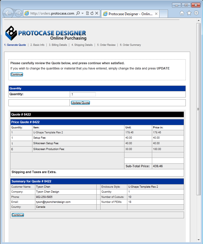
#On the '''Instant Quotes and Purchasing''' menu, choose '''Instant Quote''', '''Purchase''', or '''Create Requisition for my purchasing Department'''. | #On the '''Instant Quotes and Purchasing''' menu, choose '''Instant Quote''', '''Purchase''', or '''Create Requisition for my purchasing Department'''. | ||
| − | # | + | #;A web page page will open, guiding you through the steps to receive an instant quote or purchase your enclosure. |
| − | # | + | #;[[File:window-purchasing.png|500px]] |
Revision as of 16:15, 22 October 2015
This Quick Start guide walks you through the installation of Protocase Designer and its tools for creating, customizing, and quoting/ordering a design. For an overview of Designer features, click here.
Contents
Installing Protocase Designer
The installation process is the same for both first-time installations and upgrades.
- Before installing, ensure that your graphics card drivers are compatible with Opengl 1.2+ (such as ATI and NVIDIA) and that they are up to date.
- If you are installing Protocase Designer on a Mac OSX Mountain Lion, please follow the instructions in Installing Designer on a Mac OSX Mountain Lion.
- Close all versions of Protocase Designer before installing a new one. (If you are using Windows, when you try to install Designer while another copy is running, an error occurs and the installer exits.)
- On the [Download page], click the button for the appropriate download format. The download will begin.
- Open the Protocase Designer installer file in your Downloads folder.
- If you have previously installed Designer as the Administrator (or if your anti-virus software requires that you confirm that the file is safe), right-click the installer file in Windows Explorer and choose Run as administrator. (You might have to first choose Show in folder in Google Chrome, or Open containing folder in Firefox.)
- Follow the prompts to install.
- For first-time installations, after launching Designer, you are prompted to register. Be sure to do so, so that you can receive estimates, place an order, and access the online Cutout Library.
See Also:
Creating your enclosure
To begin designing your enclosure, select a template such as Consolet, Bracket, Panel, L shape, Rackmount, or U shape. You then customize various parameters including size, thickness, material, and color. A 3D model of your enclosure is then created, which you can customize further.
- Open Protocase Designer.
- In the Pick an Option to Start dialog box, click New File.
- Select an enclosure category on the left and then select an enclosure type.
- Modify the enclosure parameters including size, thickness, material, and color to meet your design requirements.
- Click OK to view the 3D model.


Customizing your enclosure
To customize the faces of your enclosure, you use the Face Editor, which provides many standard editing tools for creating cutouts, silkscreens, exclusion zones, and construction lines.
Add basic cutouts
- Rotate the model to show the face you want to edit by dragging in the 3D View window.
- Click Edit Face
 on the toolbar.
 - Click the face to edit.
- The Face Editor opens.
- Select a drawing tool from the Drawing toolbar.
- Draw shapes on the face to create cutouts.
- Click Accept and Close
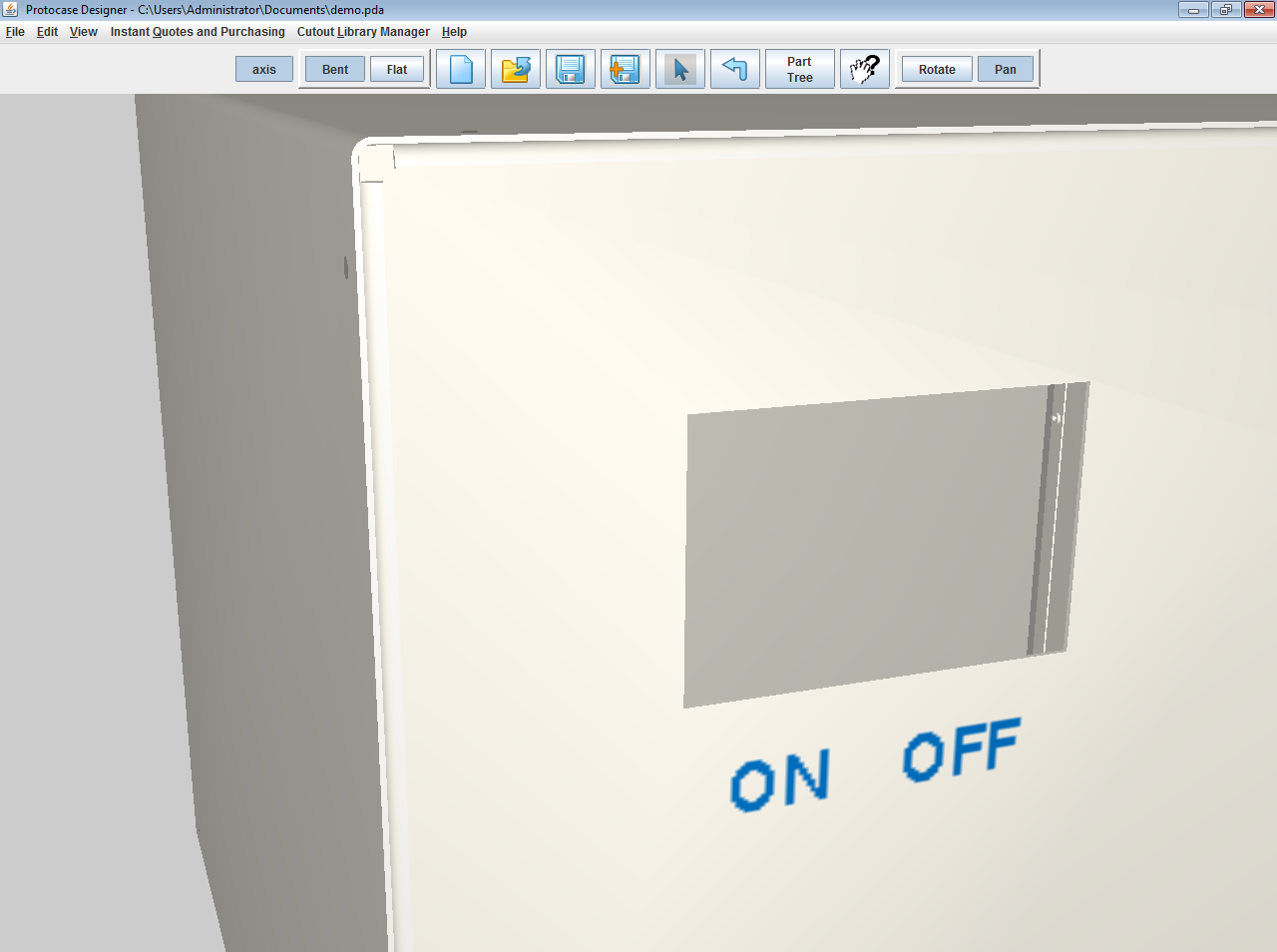
 on the toolbar. You can then see these cutouts applied to your 3D model.


Add built-in cutouts
Protocase Designer offers a variety of built-in cutouts that you can add to your enclosure.
- Click Edit Face on the toolbar and click a face to edit.
- Click Toggle Grid
 on the toolbar to show and snap to the grid.
- On the Cutout Library and Fasteners menu, point to a category and then click a cutout item.
- Click on the face to place the built-in cutout.


Add custom cutouts
You can create your own custom cutouts using the Path tool.
- Select the Path tool
 on the Drawing toolbar.
 - Click the face to place points of the path. Click the first point again to finish the path.
- Click Accept and Close to view your enclosure in the 3D View.


Note: You can quickly create complex cutouts by merging and/or trimming objects. See Using the Trim and Merge tools to create cutouts for details.
Add hardware
You can easily place hardware on your enclosure to accommodate various components, such as self-clinching fasteners (PEMs) to mount a PCB or handles.
- Click Edit Face and click a face to edit.
- Click Toggle Grid to show and snap to the grid.
- Choose Cutout Library and Fasteners > Place Self Clinching Fasteners.
- Choose the self-clinching fastener and its options.
- Click Place PEM and click the face to add the fasteners.
- Continue adding fasteners and select the Edit tool
 when you are done.
- Click Accept and Close .
- Choose Show/Hide Parts from the View menu.
- Click to clear the Cover check box.
- Rotate the model to view the fasteners.


Note: You can also create custom brackets and add them to your enclosure. See Creating and adding brackets for details.
Add silkscreen text
You can add silkscreen text for labeling items on your enclosure.
- Click Edit Face on the toolbar and click a face to edit.
- Click the Text tool
 on the Drawing toolbar.
 - Click on the face and start typing to add text.
- Click Accept and Close .
- The text is shown in the 3D model.


Note: For images with multiple or gradient colors, specify direct digital printing instead of silkscreening. Or, you can add a note to ask Protocase to use dot peening, which is a permanent marking process that does not use ink.
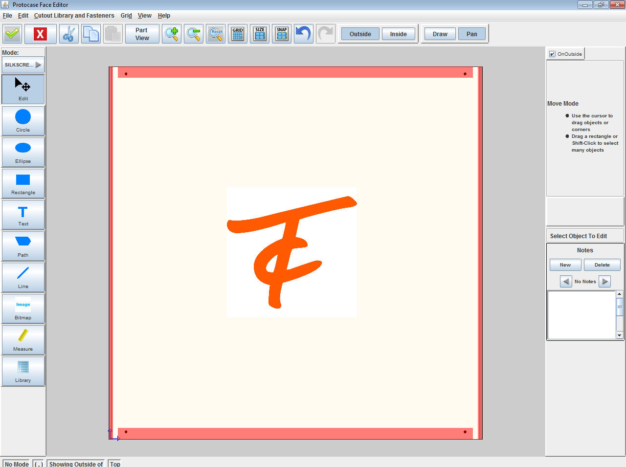
Adding an image
You can add graphics such as logos to your enclosure, using silkscreen or digital printing. See Adding silkscreening or direct digital printing for details.
- Click Edit Face and click the face to edit.
- Click the Bitmap tool
 on the Drawing toolbar, then click on the face where you want to place the image.
 - In the Open dialog that is displayed, select an image file and click Open.
- Note
- You can enter an entire path, with or without the filename, then press <Enter> or click the Open button. If you enter just the path ending with a folder, the window will list the folder files and subfolders. If you enter the path and filename, the file will open.
- Click Accept and Close to view the 3D image.
Quoting and ordering your enclosure
Once your design is complete you can instantly receive a quote and order your enclosure online.
- On the Instant Quotes and Purchasing menu, choose Instant Quote, Purchase, or Create Requisition for my purchasing Department.
- A web page page will open, guiding you through the steps to receive an instant quote or purchase your enclosure.