Creating double-d cutouts
From Protocase Designer Documentation
Double-D cutouts are commonly needed for bulkhead crimp jacks (to hold connectors) and cam lock metal punches. A double-D cutout is basically a circle cutout with two edges knocked off. When you thread a connector through the circle, the flat parts of the circle hold the connector in place. This tutorial shows the quickest, easiest way to create a double-D cutout for your Cutout Library, by joining a circle and a rectangle rather than by drawing lines. For a video of this tutorial, see https://www.youtube.com/watch?v=3gMlqGBw0Ps.
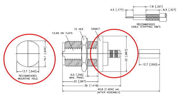
- Find a drawing of the connector and cutout, or otherwise determine its dimensions. For this tutorial, we are using the following drawing; inches, shown in the brackets, is our unit of measure. We need the width and diameter (height) of the completed mounting hole, and the diameter of the assembled connector.
- Width of completed mounting hole: 0.54"
- Diameter (height) of mounting hole: 0.634"
- Diameter of connector: 0.867"
- Launch Designer and choose Open Cutout Manager from the Cutout Library Manager menu.
- In the Library Manager window that opens, click the New Item button.
- In the New Item dialog that opens, do the following:
- In Name, enter a unique identifying name such as "Bulkhead Crimp Jack".
- In the grid of dots for Origin Placement, click the center dot. (It will turn red.) Using the center as the origin makes it easiest to place objects; you will not need a grid because you can center objects on the origin.
- Make the cutout part (canvas) as large as the connector itself, not just the hole it goes into, so that you avoid placing connectors too close together. (Think about plugs in a powerbar.) Therefore, in both Height and Width enter 0.867.
- Click OK.
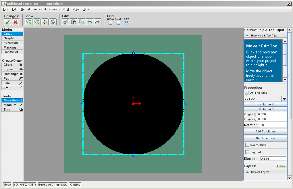
- In the Cutout Editor that opens, center the cutout in the workspace. Then click the Circle button and draw a circle. (The size and position do not matter. If you receive any placement warning, you can ignore it, then click Edit and select the circle.)
- In the Properties panel, change Origin(X) and Origin(Y) of the circle to 0.0, and change Diameter (the height of the mounting hole) to 0.634. This centers the circle on the canvas and makes it the correct size.
- Tip: Be sure to press the Enter key after changing any value in the Properties panel.
- Click the Rectangle button, then draw a rectangle. Again, the position and size do not matter right now, and you can ignore any placement warning.
- Make sure that the rectangle is selected, then in the Properties panel, change the Width to 0.54, the size of the mounting hole, and make sure that the rectangle Height is such that the rectangle overlaps both the top and bottom of the circle. (It does not matter by how much, and again you can ignore any placement warning.)
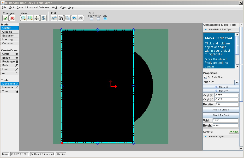
- Notice that we did not change Origin(X) or Origin(Y). The origin of a rectangle is the lower left corner, so it would not make sense to change that to 0.
- You will now align the rectangle horizontally to the circle. Click the Edit button, then hold down the Shift key while you click first on the circle and then on the rectangle. (They will both be displayed with the dashed outline.) Then click the Align centers of objects horizontally button in the Properties panel:
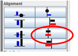
- This aligns the rectangle over the circle, and they are now both centered on the canvas.
- Important! When using the alignment tools, the first object selected becomes the anchor. If the rectangle had been selected first, then the circle would have moved instead of the rectangle.
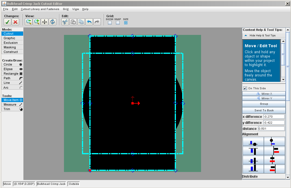
- Click the Trim button. (This button is at the very bottom of the tool panel, and might be out of sight if the window is not maximized.)
- If the Trim Mode instructions are displayed, click OK to close that window.
- The pointer icon changes to an eraser:

- You will now erase all lines that you do not want, in order to create the “D” shapes.
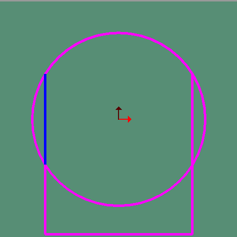
- When the eraser (pointer) gets close to a line segment, the line turns blue. Click the mouse to erase that blue segment.
- Tip: If you accidentally delete a segment, click the Undo button in the toolbar:

- Here, erasing is in progress, with a segment being selected and then erased. (In these examples, the eraser icon for the pointer is not displayed.)
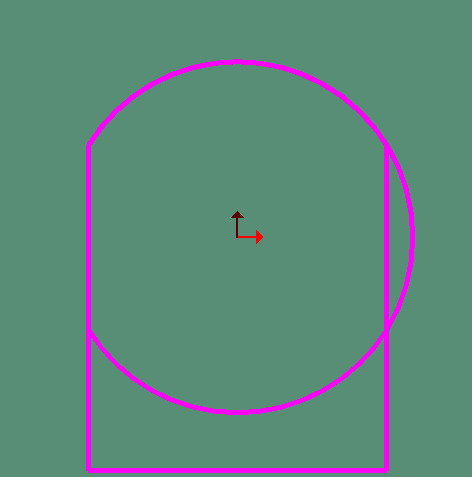
- And here it is complete:
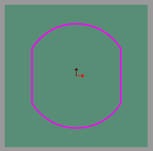
- When the trimming is complete, press the Esc key to end the Trim mode. Important! If you click the Accept and Close button now, the trims will not be saved.
- Add a circle that is an Exclusion zone the same size as the connector itself, so that nothing can be added to that area of the design that would interfere with the connector. To do this, first choose Exclusion in the Mode list.
- Now click the Circle button and draw a circle of any size and location. Center the circle by changing Origin(X) and Origin (Y) to 0 and changing the Diameter to 0.867:
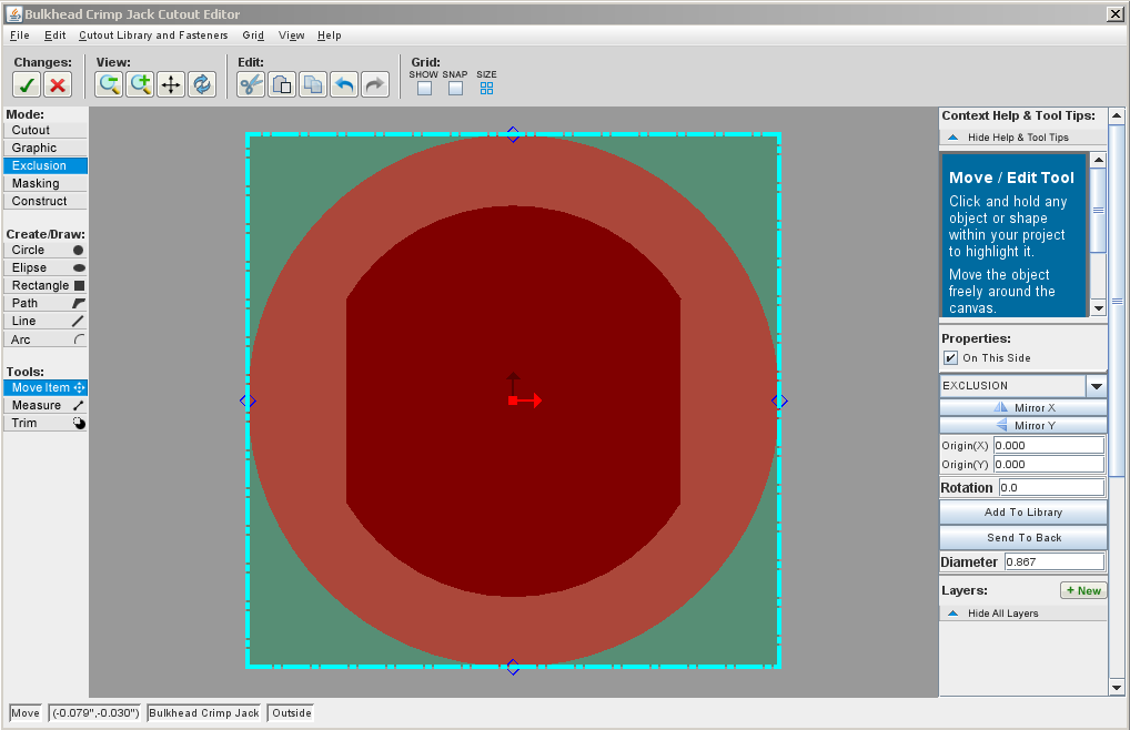
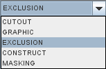
- Note: Exclusion zones are displayed in a transparent red. If you forget to select the Exclusion mode before drawing, it will be a cutout and not an exclusion zone, and will be displayed in black. You can change it to an exclusion zone in the Properties panel by clicking the Cutout dropdown and selecting Exclusion:
- Click the Accept and Close button. The cutout is now listed in the personal library section of the Cutout Library. You can now select it and place it on any enclosure, like any other item in the Cutout Library.


Related Topics