Difference between revisions of "Creating custom vents"
From Protocase Designer Documentation
m |
m |
||
| Line 19: | Line 19: | ||
#:[[File:4vent-slot-cutout5.jpg|300px]] | #:[[File:4vent-slot-cutout5.jpg|300px]] | ||
#In the Face Editor toolbar, click the '''Size''' button [[File:5Size-button.jpg]] and then click the '''Grid''' button [[File:6Grid-button.jpg]]. | #In the Face Editor toolbar, click the '''Size''' button [[File:5Size-button.jpg]] and then click the '''Grid''' button [[File:6Grid-button.jpg]]. | ||
| − | #In the Grid Size dialog that opens, enter the following values and then click OK. | + | #In the Grid Size dialog that opens, enter the following values and then click '''OK'''. |
#:Width: 0.1 | #:Width: 0.1 | ||
#:Height: 0.05 | #:Height: 0.05 | ||
| − | #: 7vent-slot-cutout6 | + | #:[[File:7vent-slot-cutout6.jpg]] |
| − | #The grid for the new item is displayed. | + | #The grid for the new item is displayed. By default, it is displayed in the lower left corner of the Face Editor screen. Click the '''Pan''' button, drag the grid to the middle of the screen, then click the '''Draw''' button. |
| − | #: 8vent-slot- | + | #:[[File:8vent-slot-cutout7a.jpg|500px]] |
#Now draw the bottom edge of the slot. Click the Path button ((8APath-button)) in the left-hand toolbar, then click on the grid at -.4, -.05, and then again at +.4,-.05. | #Now draw the bottom edge of the slot. Click the Path button ((8APath-button)) in the left-hand toolbar, then click on the grid at -.4, -.05, and then again at +.4,-.05. | ||
#: 9vent-slot-cutout8 | #: 9vent-slot-cutout8 | ||
Revision as of 16:54, 15 May 2014
THIS TOPIC IS UNDER CONSTRUCTION.
Using the Cutout tool, you can make just about any vent cutout you would like, and can use the Grid tool to place many of them quickly.
- Start a new file (from the 3D View, choose File > New), select the plain rackmount, and click OK.
- In the 3D View window that opens with the rackmount displayed, click the Select a Face to Edit button
 , then click anywhere on the front cover.
- The Face Editor opens, displaying the face of the front cover.
- Open the cutout library by choosing Cutout Library and Fasteners > Cutout Library.
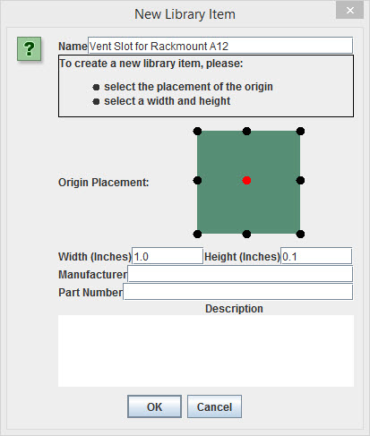
- In the Library Manager window that opens, click the New Item button.
- In the New Library Item dialog that opens, enter the following values and then click OK. (Note that inches is the UOM.)
- Name: Vent Slot (or any name you wish)
- Width: 1.0 (this is the default)
- Height: 0.1
- Origin Placement: Click the center dot.
- In the Face Editor toolbar, click the Size button
 and then click the Grid button
  .
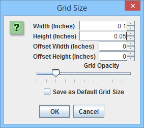
. - In the Grid Size dialog that opens, enter the following values and then click OK.
- Width: 0.1
- Height: 0.05
- The grid for the new item is displayed. By default, it is displayed in the lower left corner of the Face Editor screen. Click the Pan button, drag the grid to the middle of the screen, then click the Draw button.
- Now draw the bottom edge of the slot. Click the Path button ((8APath-button)) in the left-hand toolbar, then click on the grid at -.4, -.05, and then again at +.4,-.05.
- 9vent-slot-cutout8
- Now draw the right edge of the slot.
- Click the arc button in the right-hand context toolbar, then click on the grid at +.4, +.05.
- 10vent-slot-cutout9
- Click the Snap To Grid button ((11SNAP TO GRID BUTTON)) to turn off the automatic snapping, then click on the grid at +.45, 0.
- 12NEW STEP 10 B
- Click the arc button in the right-hand context toolbar, then click on the grid at +.4, +.05.
- Now draw the top edge of the slot.
- Click the line button in the right-hand context toolbar, and click the Snap to Grid button in the Face Editor toolbar.
- Click on the grid at +.4,-.05.
- 13NEW STEP 11B
- Now draw the left edge of the slot.
- Click the arc button in the right-hand context toolbar, then click on the grid at -.4, -.05.
- 14NEW STEP 12
- Click the Snap to Grid button to turn off the snap, then click on the grid at -.45, 0.
- 15NEW STEP 12B
- The slot drawing is complete.
- Click the arc button in the right-hand context toolbar, then click on the grid at -.4, -.05.
- In the Face Editor toolbar, click the Accept Changes and Close button ((13AACCEPT CHANGES AND CLOSE BUTTON)). The screen returns to the Library Manager, with the slot selected.
- 16NEW STEP 13
- With the vent slot selected, click the Place Item button.
- The Face Editor is displayed, with the cursor in a shape simulating the slot.
- In the right-hand context panel, change the Rotation to 45 degrees.
- Click anywhere on the enclosure.
- A cutout of the slot is added to the face, at the 45-degree angle.
- 17NEW NEW STEP 16
- In the Face Editor toolbar, click the Cut button ((18CUT BUTTON IN TOOLBAR)), then the Grid button, then the Size button.
- In the Grid Size dialog that opens, enter the following values and then click OK.
- Width: 0.2
- Height: 0.2
- In the Face Editor, move the cursor to wherever you want to place the first slot in the cutout, then click the Paste ((19PASTE BUTTON IN TOOLBAR )) button. Repeat this a number of times on one side of the enclosure at equal intervals that look nice.
- 20placing cutout at equal intervals that look nice
- Now make a mirror image, using a -45 degree angle, on the other side of the enclosure:
- Select a cutout.
- Click the Cut button.
- Click the Paste button.
- In the right-hand context toolbar, change Rotation to -45.
- Copy as needed to match the first set.
- The vent is now complete.
- Click the Accept Changes and Close button. The vent is shown in the 3D View.
- Choose File > Save. If you have not yet named the enclosure design file, do so now.


Note: You can save a template of the complete vent to use again in other enclosure designs:
- Click the Edit button from the left-hand toolbar and then select the vents.
- Right-click the group of vents and click Group in the right-hand context menu.
- Click the Add to library button.
- In the dialog that opens, name and save the group.
You can now choose this vent design from the Cutout Library to add to any enclosure.