Difference between revisions of "Creating a custom cutout for a connector"
From Protocase Designer Documentation
m (→Draw cutouts) |
m (→Draw cutouts) |
||
| Line 12: | Line 12: | ||
#Enter a name for the cutout. | #Enter a name for the cutout. | ||
#If you want to change the default origin (shown as a red dot), in '''Origin Placement''' click the dot that you want to be the origin. (It will turn red.) | #If you want to change the default origin (shown as a red dot), in '''Origin Placement''' click the dot that you want to be the origin. (It will turn red.) | ||
| − | #Enter the '''Width''' and '''Height''' of the bounding box for your cutout. (If | + | #Enter the '''Width''' and '''Height''' of the bounding box for your cutout. (If the cutout is to be a group of objects, all objects must fit within this box.) |
#(Optional) Enter the '''Manufacturer''', '''Part Number''' and/or '''Description'''. | #(Optional) Enter the '''Manufacturer''', '''Part Number''' and/or '''Description'''. | ||
#Create your cutout using the drawing tools, which include printed or silkscreened text and images. | #Create your cutout using the drawing tools, which include printed or silkscreened text and images. | ||
Revision as of 18:28, 23 February 2016
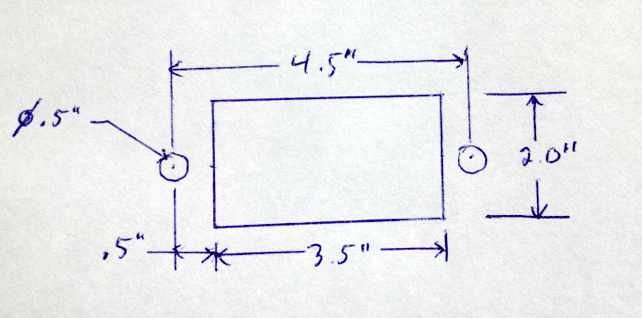
Determine mounting specifications
Draw cutouts
You can create the cutout for the connector directly in the Cutout Library, or you can create it in the Face Editor and then add it to the library. This tutorial shows you how to create the cutout in the library.
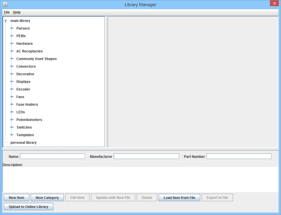
- On the 3D View toolbar, choose Cutout Library Manager > Open Cutout Manager. The Library Manager dialog opens.
- Click New Item. The New Item dialog opens.
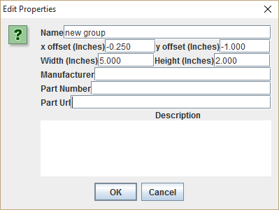
- Enter a name for the cutout.
- If you want to change the default origin (shown as a red dot), in Origin Placement click the dot that you want to be the origin. (It will turn red.)
- Enter the Width and Height of the bounding box for your cutout. (If the cutout is to be a group of objects, all objects must fit within this box.)
- (Optional) Enter the Manufacturer, Part Number and/or Description.
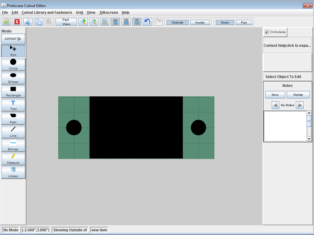
- Create your cutout using the drawing tools, which include printed or silkscreened text and images.
- Click Accept & Close.

- The custom cutout is added to the bottom of the Cutout Library > personal library list.
See Also:


