Creating a custom cutout for a connector
From Protocase Designer Documentation
Revision as of 17:16, 25 February 2016 by Stownsend (talk | contribs) (→Create the connector cutout in the Face Editor)
Determine mounting specifications
- Determine the mounting specifications (mounting hole and cutout dimensions) for the connector.

The cutout for the connector is 3.5" long and 2" high, and the mounting holes are 0.5" in diameter and are set 0.5" from the left and right edges of the connector cutout.
Create the connector cutout in the Face Editor
You can create cutouts directly in the Cutout Library, or create them in the Face Editor and then add them to the Library. This tutorial will create the cutout in the Face Editor.
- In the Face Editor, set the grid to 0.25" x 0.25".
- Click the Grid
 button. This displays the grid, and also causes objects to snap to the grid.
 - To draw the connector cutout, draw a rectangle (anywhere will do, but near the middle of the screen is easiest).
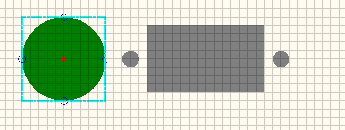
- Click the Edit tool and, with the rectangle selected, in the Properties panel set Width to 3.5" and Height to 2.0".
- To draw the mounting holes, draw a circle that snaps to the center of one edge, 0.5" from the edge.
- Copy and paste the circle to the opposite side.
- To check the measurements, click the Measure tool and measure from the center of the lefthand hole to the center of the righthand hole. The distance shown in the Properties panel should be 4.5", as indicated in the original drawing.
- When grouping objects, the origin of the first cutout you select becomes the origin of the group. If you draw an edit box around the objects, the first cutout and therefore the group origin will be random, but if you hold down <Shift> and select each cutout, the origin of the first cutout you select will be the group origin. To move the origin of the final cutout to a particular location, create a Construct circle over the point you wish to be the origin and choose it first when creating your group. In this tutorial, you will place the origin at the center of the final grouped cutout.
- Choose the Construct mode.
- Click the Circle tool and draw a circle anywhere on the canvas, but large enough so that it will stick out past the top and bottom of the rectangle, so that you will be able to select it later. (You need to do this because currently objects drawn in the Construct mode are not visible on top of other objects. This is a defect that will be fixed in an upcoming release.)
- Click the Edit tool.
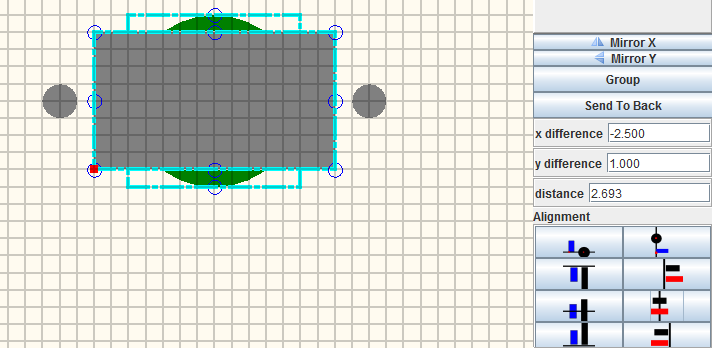
- Hold down the <Shift> key and click first the rectangle, then the construct circle.
- Click the Align Centers of Objects Vertically button
 , then click the Align Centers of Objects Horizontally button
  . The construct circle is now centered in the rectangle.
- Click anywhere on the canvas (to clear the edit selections).
- Hold down <Shift> key and select first the construct circle and then the rest of the cutouts.
- Click the Group button in the Properties panel.
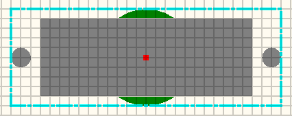
- Notice that the origin is now shown in the center of the group. The green construct circle will always be displayed with the cutout, but it will never interfere with anything.
- Click the Add to Library button in the Properties panel.
- In the Edit Properties dialog that opens, enter a Name for the cutout.
- Note: If you wanted the cutout origin to be the lower left corner of the grouped cutout, you could change x offset and y offset to 0.
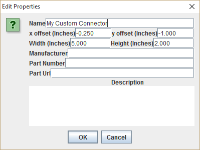
- Click OK.
- The connector cutout is now available in your personal library section of the Cutout Library, and can be added to any face.


See Also: