Difference between revisions of "Face Editor"
m (→Creating and adding brackets) |
m (→Creating and adding brackets) |
||
| Line 584: | Line 584: | ||
#:You are prompted to select the face that is the mating face (that mounts onto the enclosure). Click '''OK''' and then do so. | #:You are prompted to select the face that is the mating face (that mounts onto the enclosure). Click '''OK''' and then do so. | ||
#:The New Library Item dialog opens. | #:The New Library Item dialog opens. | ||
| − | #:[[File: | + | #:[[File:New_library_item_dialog.jpg|200 px]] |
| − | #You can | + | #You can enter or edit the following information for the bracket: |
#'''Name''': Note that the default name provides a description of the mating face (such as "U Shape by Left Side - Bottom" or "U Shape by Left Side - Bottom"). | #'''Name''': Note that the default name provides a description of the mating face (such as "U Shape by Left Side - Bottom" or "U Shape by Left Side - Bottom"). | ||
#:'''Manufacturer''' (optional) | #:'''Manufacturer''' (optional) | ||
| Line 592: | Line 592: | ||
#Click '''OK.''' | #Click '''OK.''' | ||
#:You receive a message that the bracket has been added to your library. It is now listed in the '''Cutout Library and Fasteners''' menu.<br><br> | #:You receive a message that the bracket has been added to your library. It is now listed in the '''Cutout Library and Fasteners''' menu.<br><br> | ||
| − | '''Note On Bracket Origin''' | + | #:'''Note On Bracket Origin''': The default origin for placement is the default origin of the bracket template. In the 3D View, the bracket origin is displayed with a red dot and arrows. In the Face Editor, the bracket origin is displayed with blue arrows. The '''x''' and '''y''' values in the Properties panel refer to this origin.When you are adding the bracket to an enclosure, when you click the location on the enclosure face, the origin point of the bracket will be placed precisely where you click.<br><br> |
| − | The default origin for placement is the default origin of the bracket template. In the 3D View, the bracket origin is displayed with a red dot and arrows. In the Face Editor, the bracket origin is displayed with blue arrows. | ||
'''''To place a bracket on the enclosure''''' | '''''To place a bracket on the enclosure''''' | ||
Revision as of 15:50, 23 October 2014
Contents
- 1 Face Editor overview
- 2 Viewing the face
- 3 Coordinate System
- 4 Drawing shapes
- 4.1 Selecting the drawing mode
- 4.2 Draw circles
- 4.3 Draw ellipses
- 4.4 Draw rectangles
- 4.5 Draw squares
- 4.6 Draw custom paths
- 4.7 Draw lines
- 4.8 Add text
- 4.9 Add images
- 5 Measuring distances
- 6 Using the grid
- 7 Managing object properties
- 8 Adding cutouts
- 9 Adding hardware
- 10 Manipulating objects
- 11 Printing one or more faces on paper for review
- 12 Exporting and importing face templates
- 13 Face Editor preferences
Face Editor overview
The Face Editor allows you to customize the faces of your enclosure using standard editing tools for creating cutouts, silkscreens, exclusions zones, and construction lines.
- A. Standard Toolbar
- Contains common commands such as Cut Copy, Paste, Undo, Redo, as well as zoom and grid related commands.
- B. Drawing Toolbar
- Contains tools to draw shapes, add text, and add images to the face.
- C. Viewport
- Working area that shows a 2D view of your enclosure face.
- D. Status bar
- Displays the currently selected view, X- and Y coordinates of the pointer, side of face showing (outside or inside), and the name of the face.
- E. Help pane
- Displays contextual help that changes based on the selected drawing tool.
- F. Properties pane
- Displays properties that can be changed for the selected object.
Viewing the face
Panning
To Pan the face, do one of the following.
Method 1
- In the viewport, click the wheel button and drag to pan the model to the desired location.
Method 2
- On the Standard Toolbar, click Pan.
- In the viewport, left-click and drag to pan the model to the desired location.
Method 3
- Press and hold the Alt key.
- In the viewport, right-click and drag to pan the model to the desired location.
Zooming
To Zoom in or out, do one of the following:
Method 1
- Rotate the wheel button forward or backward.
Method 2
- On the Standard Toolbar (or on the View menu), click Zoom In or Zoom Out.
- Click within the viewport to incrementally zoom the model in or out.
Method 3
- On the Standard Toolbar, click Zoom In.
- Drag a diagonal selection within the viewport to zoom in to a desired area of the model.
Note: The model moves toward the mouse pointer when zooming out and away from the mouse pointer when zooming in.
Resetting the view
The Reset View command displays the face in the centre of the viewport at its original zoom level.
Do one of the following:
Method 1
- On the Standard Toolbar, click Reset View.
Method 2
- On the View menu, click Reset Zoom to display the model in its original orientation.
Coordinate System
The origin in the Face Editor is located at the absolute coordinate system of the model. The x- and y-coordinates for each face are referenced from the absolute origin and always increase moving away from the origin. The figure below shows examples of the coordinate system for several faces on a U-Shape enclosure.

Choosing the Units of Measure
You can set the default unit of measure.
- Choose Preferences from the Edit menu.
- Click the down-arrow for Display Units.
- Select the unit of measure (INCHES, CM, or MM).
- Click OK.
Drawing shapes
Selecting the drawing mode
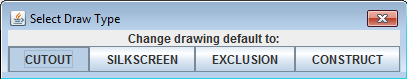
Selecting the drawing mode determines the type of objects created: Cutout, Silkscreen, Exclusion, Construct, and, if the enclosure metal is anything other than Cold Rolled Steel, Masking.
- On the Drawing Toolbar, click the button under the "Mode" label; by default, the button is set to Cutout.

- A popup window opens:
- or (if the enclosure metal is not Cold Rolled Steel):
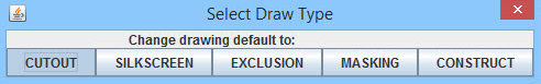
- Click the button for the drawing type you want to set as the default. The selected button changes color to indicate the current default drawing mode.


Using the Cutout drawing mode
The Cutout drawing mode allows you to draw shapes on your enclosure for accommodating connectors, switches, ports, etc. You can also draw custom shapes to create cutout logos and images.
Editing cutouts: Cutting into the perimeter of a face
You can create cutouts in any edge of a face, including where two faces meet.
- In the Face Editor, make sure that the mode is set to CUTOUT.
- Place or draw a cutout so that it intersects a boundary of the face.
- A placement warning is displayed, with three options:
- Accept this placement
- Reject this placement
- Cut Face using this placement
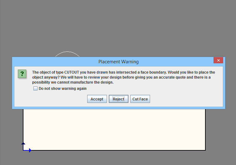
- Note A placement warning is not an error message. You can cut into a boundary, which is always displayed in black. You cannot cut into an exclusion zone, which is always displayed in red.
- A placement warning is displayed, with three options:
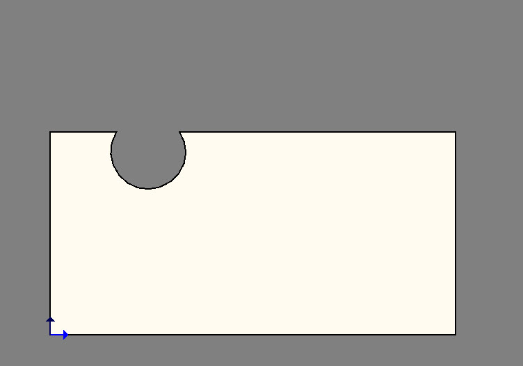
- Click the Cut Face button.
- The face edge is cut out:


See Also:
Using the Silkscreen drawing mode
The Silkscreen drawing mode lets you add images and text to the enclosure, for silkscreening or for direct digital printing. Silkscreening is limited to specific colors; direct digital printing can print any number of colors, including gradients, with precise rendering. Note that you cannot apply both silkscreening and digital printing to the same face. For complete details on silkscreening, please see About Silkscreening.
Adding silkscreening or direct digital printing
Important! You cannot use digital printing on metal if the color is "None"; it does not stick to bare metal. You can, however, use silkscreening on bare metal.
- In the Face Editor, choose the face you want, and then click the Text button.
- The Silkscreening or Direct Digital Printing message window opens, alerting you that you must select silkscreening or direct digital printing for each face, and summarizing the advantages and costs of each method.
- Note: This message also opens whenever you first place a silkscreen object (text, bitmap, or, when Mode is set to "Silkscreen", any shape) on a face.
- Click OK to close the window.
- The Silkscreen or Direct Digital Printing dialog opens:
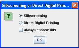
- Select either the Silkscreening or Direct Digital Printing radio button.
- To specify either method for all faces of the enclosure, select the always choose this check box.
- Note: You can also specify the default printing type in the new Graphics Type field in Preferences.
- Add text and/or images to the face.

Limitations of direct digital printing
- The printer can print only on the top face of a part not more than 6" high, 10" wide, and 24" long.
- The face and all its attachments must be entirely flat. Nothing can stick up above the surface.
- The inside of the face cannot be printed.
- The enclosure must have a color. (None refers to bare metal, and the paint will not stick.)
To change from one printing method to the other
- In the Face Editor, select the face that you want to change.
- Choose the Convert... command from the Silkscreen menu.
- Note: There is no separate menu for digital printing; the Silkscreen menu is used for both. If the items you chose are currently silkscreened, the Convert to Direct Digital Printing command is listed in the menu. If the items you chose are currently digital, the Convert to Silkscreen' command is listed in the menu.
- If you choose Convert to Silkscreen, a confirmation window opens. Click Yes to confirm the conversion to stock silkscreen colors.
See Also:
Using the Exclusion drawing mode
The Exclusion drawing mode allows you to add shapes to your enclosure to mark areas where other objects cannot be added.
Using the Masking drawing mode
The Masking drawing mode lets you specify masking on any metal except cold rolled steel (which would rust). Masking is the process in which Protocase puts tape over a spot before painting it, so that it stays bare. This is usually done to make a bare spot for an electrical ground.
- Select the enclosure template you want to use.
- In the New Assembly from Template dialog, change MetalType to any type other than Cold Rolled Steel. (Aluminum is the most common metal that is masked.)
- Select the face you want to add masking to.
- In the Mode menu, click the Masking button.
- Choose a shape (preferably Rectangle) and draw the spot(s) you want masked.

Using the Construct drawing mode
The Construct drawing mode lets you draw shapes on your enclosure for use as reference when creating cutouts, silkscreen or exclusion zones, as well as when placing hardware.
Draw circles
Available in all drawing modes. Template:Procedure
Draw ellipses
Available in all drawing modes. Template:Procedure
Draw rectangles
Available in all drawing modes. Template:Procedure
Draw squares
Available in all drawing modes.
Method 1
Method 2
Draw custom paths
Available in all drawing modes. Template:Procedure
Creating an arc using the Path tool
Path editing: Using the Trim and Merge tools to create cutouts
The Trim and Merge tools provide quick ways to create paths for cutouts. The Merge tool lets you create an outline (path) by merging multiple shapes. The Trim tool lets you delete lines in intersecting shapes to create the path you want.
To merge two or more objects
- Place two or more objects on a face, each overlapping at least part of one other object.
- Click the Edit button and select all the objects you want to merge. (If you select an object by accident, you can remove it by holding down the Shift key and clicking the object you accidentally selected.)
- Right-click within the selection and choose Merge from the popup menu.
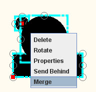
- The objects are merged into a single cutout.


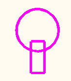
To edit a merged object If you select a merged object, each node in what is now a single object can be dragged to further change the object shape. In this example, the selected node (colored red) is being dragged up and to the right.


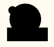
To trim two or more objects In this example, a key slot is created with the Trim tool.
- Place a circle on the face.
- Add a rectangle to the bottom of the face, overlapping it.
- Click the Edit button and select both objects.
- Click the Trim button.
- The outline of each object is outlined, the cursor icon turns into an eraser (not shown in these examples).
- Use the eraser to eliminate the lines you do not want.
- When you are done, press the Esc key on your keyboard, or click any other button in the Drawing toolbar.
- The remaining path is now a cutout and is displayed as such.


- Tip: A notch could have been created by removing different lines in the same overlap:

See Also:
Draw lines
Available in all drawing modes. Template:Procedure
Add text
Available in Silkscreen ![]() drawing mode only.
drawing mode only.
- Note: Selecting the Image Tool will switch the drawing mode to Silkscreen, regardless of the current drawing mode.
Note: Unicode characters (language scripts, punctuation marks, diacritics, mathematical and technical symbols, etc.) are supported.
Add images
Available in Silkscreen ![]() drawing mode only.
drawing mode only.
- Note: Selecting the Image Tool will switch the drawing mode to Silkscreen, regardless of the current drawing mode.
- Note: Colors are automatically adjusted to match stock Protocase silkscreen colors.
Measuring distances
Use the Measure tool to determine the distance between two points on objects or anywhere on the face.
- On the Drawing toolbar, select the Measure tool.

- On the Properties panel, do one of the following:
- Click Snap to force measurements from key points (corners and centres) on objects
- Click Free to allow measurements from any point
- Click to place the start point.
- Click to place the end point. The x, y, and total distances are displayed on the Properties panel.
- Continue measuring distances and select the Edit tool
 when you are done.
Measuring distance between objects
See Also:
- Using the Measure tool to specify both distance and alignment between objects
- Using the Measure tool to move an object a specific distance from another object
- Dimensions: Displaying measurements for review
Using the Measure tool to move an object a specific distance from another object
You can use the Measure tool to move an object a specific distance from another object. This example shows how to move the centre of a circle cutout 5 inches to the right and 3 inches below the corner of a rectangle cutout.
- Note: The distances are measured from the bottom-right corner of the rectangle cutout to the center of the circle cutout in the direction of the coordinate system at the bottom left (positive x values move up and positive y values move right).
See Also
- Measuring distances
- Using the Measure tool to specify both distance and alignment between objects
- Dimensions: Displaying measurements for review
Using the Measure tool to specify both distance and alignment between objects
You can use the Measure tool to specify both distance and alignment between objects. Once you determine the absolute coordinate for one object, the Measure tool lets you place all other objects relative to that, including objects (such as cutouts) on opposite faces.
To align two objects at a specific distance and angle
- On the Drawing toolbar, click the Measure button.
- On the face, click the start point (the object or location that is to be the reference point).
- On the face, click the end point (the object or location that is to be placed in reference to the starting point).
- An arrow is displayed that points to the item that will change, and the Properties panel displays the x difference, y difference, and distance.
- Note: When the Properties panel displays a negative value, it is indicating that the difference is in the opposite direction of the coordinate system.
- Edit the x difference and/or y difference to position the second point in relation to the first. For example, to position an object one inch away from an existing object along both the X and Y axes, enter a y difference of "01" and an x difference of "01".
- Note: To align objects horizontally or vertically without measuring or changing the distance between them, click the Edit button and use the alignment shortcuts in the Properties panel.
- Note: If you do not need to specify a distance between two objects, you can use just the Alignment tools in the Properties panel to align them.
To align two objects on opposite faces
- For a detailed tutorial, please see Aligning cutouts on opposite faces, which uses the absolute origin as the reference point. When using the Measure tool, you can use any reference point you wish as the origin.
See Also
- Using the Measure tool to move an object a specific distance from another object
- Measuring distances
- Dimensions: Displaying measurements for review
Display measurements
You can display the distance between any two points in the Face Editor, using the Dimension button. You can then take a screenshot with the measurements displayed, for peer reviews or other purposes.
To measure and display the distance between two points
- Display the face you want to edit.
- In the Face Editor, click the Dimension button in the Drawing toolbar.

- The distance of "0.000" is displayed at cursor, which is the current endpoint.
- Click the first endpoint of the distance you wish to measure, then move the cursor.
- As you begin to move the cursor, the distance between the endpoint and the cursor position is displayed.
- If you make an error, click the Undo button in the Face Editor toolbar.
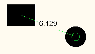
- When the cursor is near an object, it snaps to the important points of the object (its center, or one of the compass points on its outline), a green circle is drawn around the snap-to point, and the lines turn green.
- The lines turn red when the measurement does not have any meaning. There are only three types of measurements that have meaning:
- The distance between the two points;
- The distance in the x axis (when the lines are vertical and the arrows are horizontal); and
- The distance in the y axis (when the lines are horizontal and the arrows are vertical).
- Click the second endpoint of the distance you wish to measure.
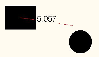
- A second line parallel to the first line is drawn, and the distance between the lines is displayed. The displayed distance changes as you move the cursor. This example shows the distance between the parallel centers of the square and the circle.
- When the lines and distance are the way you want them, click the mouse.
- The displayed lines and measurements are saved to the face, and the measurement is reset to 0.000 at the cursor position. You can add more measurements to the screen in this way.
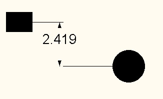
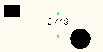
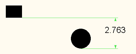
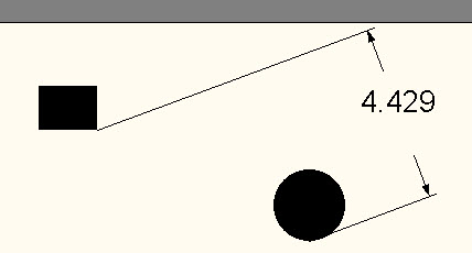
- Tip: You can display the measurement with the lines at an angle to their endpoints. For example, here the distance is shown between the bottom of the rectangle and the bottom of the circle:
- and here the user drags the cursor to a position at an angle:


To delete a displayed measurement
Do either of the following:
- Right-click one of the lines in the measurement and choose Delete from the floating menu.
- Highlight the line and press the Delete key (on your keyboard).
See Also
- Measuring distances
- Using the Measure tool to move an object a specific distance from another object
- Using the Measure tool to specify both distance and alignment between objects
Using the grid
The grid is useful to help accurately place and align objects.
Turn on/off the Grid
- Do one of the following:
- On the Standard toolbar, click Toggle Grid.

- On the Grid menu, click Toggle Grid.
- On the Standard toolbar, click Toggle Grid.
- Repeat to toggle the state of the grid.
- Note: Snap to Grid option is automatically enabled when the grid is turned on.

Turn on/off Snap to Grid
Change grid size and offset
- On the Standard toolbar, click
 or choose Grid Size from the Grid menu.
 - In the Grid Size dialog that opens, change any of the following values:

- Width: Horizontal distance between grid lines.
- Height: Vertical distance between grid lines.
- Offset Width: Horizontal offset of grid lines from default grid position.
- Offset Height: Vertical offset of grid lines from default grid position.
- Grid Opacity: Opacity of the grid lines. Move the slider to left for lighter lines or the right for darker lines.
- Save as Default Grid Size: Use the current grid size when editing all faces in the Face Editor Window.
- Note: If you change the Grid Size and do not check Save as Default Grid Size, the grid will revert back to the default size after closing the Face Editor, even if you re-open the same face.

Managing object properties


Top of Properties Panel
Applies to all objects, including silkscreen.
- Click the line that reads "Click to Expand Context Help" to read usage tips for the current object you are editing (circle, ellipse, text, etcetera). Click anywhere in the upper panel again to hide the help.
- For help on the Layers buttons and its toolbar, please see Adding and managing layers.
- The checkbox "On This Side" is selected when the object is on the side that you are editing. Clear the check box to move the object to the other side of the face. Note: The wording of this check box has been changed. Prior to version 4.4.6, it was labeled "OnBottom."
Fill
Applies to silkscreen and construction objects including circles, ellipses, rectangles, and paths.
- Select the check box to fill in the object. The line thickness option is not available when the check box is selected.
Line Thickness
Applies to silkscreen and construction objects including circles, ellipses, rectangles, paths, and lines. Also applies to lines of all object types.
- Select a value from the list below the Filled check box.
Color
Applies to silkscreen objects including circles, ellipses, rectangles, paths, lines, and text.
- Select a color from the Color menu.
- Refer to Stocked Silkscreening Colors for a list of available colours.
Type
Applies to all objects.
- Change the object type by selecting a different type from the list.
- Object types include:
- Cutout
- Silkscreen
- Exclusion
- Construction
Origin
Applies to all objects.
- Change the location of the X and Y origins with respect to the absolute coordinate system.
- Enter a number and press the Tab key to accept.
- The origin of an object is indicated by a red square.
- The origin for each object is determined as follows:
- Circles -- centre
- Ellipses -- centre
- Rectangles -- corner closes to the absolute origin
- Text -- bottom left corner
- Paths -- start point
- Lines -- start point
- Images -- bottom left corner
- Tip: You can right-click any object to open a Properties dialog where you can change its absolute origins, Rotation, Height, and/or Width.
Size
Applies to all objects (options displayed depend on object selected).
- All values use the default Display Units, unless otherwise specified. See Preferences [add link] to change the default Display Units.
Circles
- Radius, Diameter -- Changing one of these properties will automatically update the other. Diameter is twice the radius.
Ellipses
- RadiusX -- Radius along X-axis (defines horizontal length).
- RadiusY -- Radius along Y-axis (defines vertical length).
Rectangles
- Width, Height -- Width and Height of the object.
- Rotation -- Angle with respect to origin in degrees. Positive value rotates object clockwise and negative value rotates object counter-clockwise
Text
- Rotation -- Angle with respect to origin in degrees. Positive value rotates object clockwise and negative value rotates object counter-clockwise
- Font -- Change the font to Arial, Courier, Garamond, Avant Garde, Times New Roman, Palatino, or Bookman.
- Font Size -- Change the font size within the available range of 7–99.
- Font Style -- Change the font style to Regular, Bold, Bold Italic, or Italic.
- Text -- Change the text to appear on the face. Press the Tab key to accept.
Path
- Rotation -- Angle with respect to origin in degrees. Positive value rotates object clockwise and negative value rotates object counter-clockwise
Lines
- Length -- Distance from origin to end point.
Images
- Width, Height -- Width and height of the object.
- Rotation -- Angle with respect to origin in degrees. Positive value rotates object clockwise and negative value rotates object counter-clockwise
Adding notes to objects
You can add Notes to objects to communicate your design intentions to the Protocase tech team. For example:
- "Round the corners of this rectangle to a radius of .05 inches."
- "Put a hinged door over this cutout."
- "Put rubber feet on this face.”
Each note is related to one specific object. Each object can have multiple notes.
Important! If your notes result in significant design changes (such as a request for a non-stocked item), the quote that Protocase Designer generates automatically might not be accurate. The quote the tech gives you after you submit the file will be correct.
To add a note to an object
- In the Face Editor, select the object that needs a note. The Properties panel then displays the Notes tools:
- Type the note in the blank text window. If the object already has a note, it will be displayed in the text window; to add another note to the object, click the New button, which clears the text window so you can enter another note.
- Every note you enter is saved with the object. If the object has multiple notes, use the forward and back arrows to view them. You can edit each note at any time.
- Every note you enter is saved with the object. If the object has multiple notes, use the forward and back arrows to view them. You can edit each note at any time.

To delete a note
- Display the note, then click the Delete button.
To review all notes for a design
- In the 3D Editor, select View > View Notes. The Notes Viewer window opens, where you can see all notes for all faces at a glance.
- To go to the object and its notes in the Face Editor, highlight any note for the object, then click the Go to Face button. The Face Editor will open, with the object selected.

Known Limitations in the Notes Viewer
- The "UNVIEWED" notation on each note listed is for internal use only. This will be corrected in a future release, and the notation will not be displayed.
- The Name, Part Number, Manufacturer, and Description fields are also for internal use only. They should be automatically populated with the object specifications, but are not. Any text you enter in the fields will be lost when you close Designer. This will be corrected in a future release.
Adding cutouts
You can add a variety of built-in and custom cutouts to your enclosure.
- On the Standard toolbar, click Edit Face
 and click a face to edit.
 - On the Cutout Library and Fasteners menu, point to a category and then click an item.
- Click on the face to place the built-in cutout.


See Also:
- Using the Cutout Library Manager to create and edit cutouts
- Importing DXF cutout files
- Drawing cutouts
Adding "D" ports
You can add a "D"-shaped port (a circle with one side flattened) to your enclosure design.
- In the Face Editor, choose Place DPort from the Cutout Library and Fasteners menu and place it on the face.
- The D-cutout is added in a default size.
- To edit the cutout, right-click the cutout and choose Properties. (The Radius and Edge Length are not currently available in the right-hand Context panel.)
- The Properties panel opens.
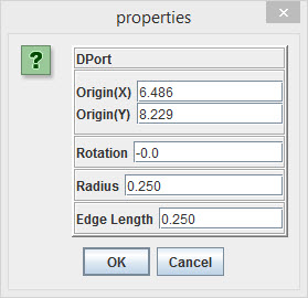
- To change the radius of the circle, edit Radius.
- To change the length of the straight cut, edit Edge Length.
- To change the position, use the Origin(X) and Origin(Y) fields.
- To rotate the cutout, in the Rotate field enter the degrees, preceded by a negative sign if you want to rotate it counter-clockwise.
- Note Incorrect error messages might be displayed for the D cutout, such as "Some objects may be outside the face boundary or overlapping keepout zones after this operation." Do a visual check on the design in the Face Editor and/or 3D View, and if it seems correct to you, ignore the message.

Adding countersinks and tapped holes
Important! Tapping holes in thin sheet metal is not recommended, since it is too thin for threads. Please consider using a Self Clinching Nut instead.
To add a countersink to a face
- In the Face Editor, choose the face you want, and draw a circle for the countersink hole.
- Select the new Countersink check box in the Properties panel.
- The Select Thread dialog opens, where a default Thread Size is displayed.
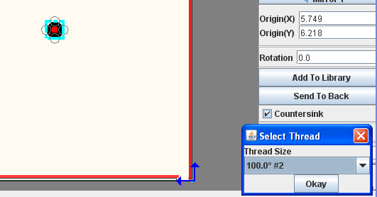
- Click OK to select the default, or click the down-arrow to select a different size and then click OK.
- Note: Thread Size includes the angle of the countersink on the head, and the standard thread size. For example, a thread size of "100.0° #2" indicates a countersink angle of 100 degrees, with the standard #2 thread size.)
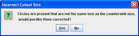
- If you chose a countersink size that is not the same size as the hole, a warning message is displayed and you are given the option to correct it. Click Yes to have the hole size changed to match the selected countersink size. Click No if you want a different tolerance than is specified for the screw.
- The countersink is drawn on the face.


To add multiple countersinks to a face
- To add multiple countersinks to a face at one time, draw a circle for each hole, click the Edit button, select all circles, and then click the Countersink check box.
To add a tapped hole to a face
- In the Face Editor, choose the face you want, and draw a circle for the tapped hole.
- Select the new Tapped check box.
- The Select Thread dialog opens, where a default Thread Size is displayed.
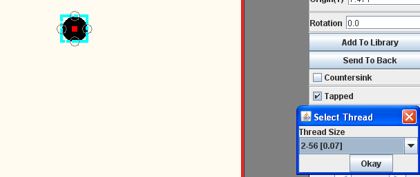
- Click OK to select the default, or click the down-arrow to select a different size and then click OK.
- Note: Thread Size includes the hole diameter along with the standard screw types. For example, a thread size of "2-56 [0.07]" indicates the standard 2-56 screw type with a diameter of 0.07" for the threaded hole. The minor diameter is used along with some tolerance so that it does not bind.
- If you chose a thread size that is not the same size as the circle, a warning message is displayed and you are given the option to correct it. Click Yes to have the circle changed to match the selected thread size. Click No if you want a different tolerance than is specified for the screw.
- The tapped hole is drawn on the face.

To add multiple tapped holes to a face
- To add multiple tapped holes to a face at one time, draw a circle for each hole, click the Edit button, select all circles, and then click the Tapped Hole check box.
Creating and adding brackets
You can create customized brackets with cutouts and other elements and save them to the Cutout and Fasteners Library. You can then add them to enclosures at any point.
To create a bracket
- Click New.
- The New Assembly from Template dialog opens.
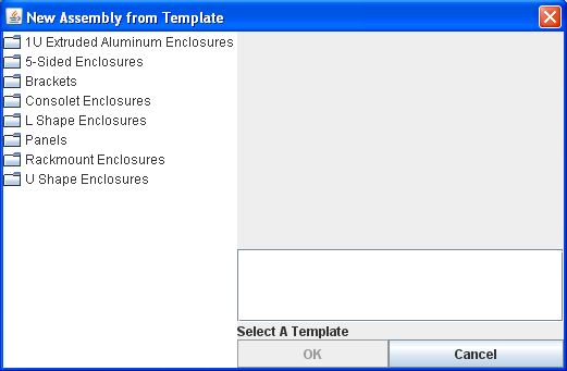
- Choose the bracket that you want to customize, and then edit its parameters (Width, Depth, Height, etc.) as necessary.
- Add elements (cutouts for mounting, standoffs, etc.) as necessary to each face. When done, click the Accept Changes button.
- The 3D View window opens.
- Choose Create Subassembly from the Cutout Library Manager menu.
- You are prompted to select the face that is the mating face (that mounts onto the enclosure). Click OK and then do so.
- The New Library Item dialog opens.
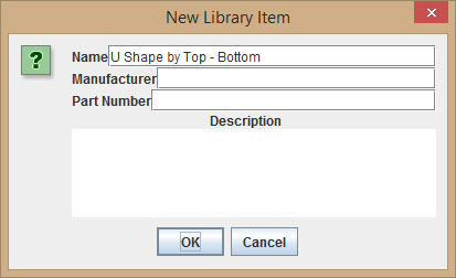
- You can enter or edit the following information for the bracket:
- Name: Note that the default name provides a description of the mating face (such as "U Shape by Left Side - Bottom" or "U Shape by Left Side - Bottom").
- Manufacturer (optional)
- Part Number (optional)
- Description (optional)
- Click OK.
- You receive a message that the bracket has been added to your library. It is now listed in the Cutout Library and Fasteners menu.
- Note On Bracket Origin: The default origin for placement is the default origin of the bracket template. In the 3D View, the bracket origin is displayed with a red dot and arrows. In the Face Editor, the bracket origin is displayed with blue arrows. The x and y values in the Properties panel refer to this origin.When you are adding the bracket to an enclosure, when you click the location on the enclosure face, the origin point of the bracket will be placed precisely where you click.
- You receive a message that the bracket has been added to your library. It is now listed in the Cutout Library and Fasteners menu.


To place a bracket on the enclosure
- Load the enclosure and select the face to which you will add the bracket.
- In the Face Editor, make sure the correct Inside or Outside is selected for the bracket placement.
- From the Cutout Library and Fasteners menu, choose Cutout Library. The Library Manager window opens; select the bracket that you want to add to the enclosure. (The customized brackets that you saved to the library are listed in the personal library section.)
- Click the Place Item button.
- The footprint (outline) of the mating face is displayed, so that you can see how to place it.
- Move the cursor (the bracket outline moves with it) to the desired location and click to drop it there. You can add multiple brackets in this way.
Adding hardware
You can easily add hardware on your enclosure to accommodate various components, such as self-clinching fasteners to mount a PCB or handles. Protocase uses common PEM® brand self-clinching fasteners.
Add self-clinching fasteners
Add mounting hardware
Manipulating objects
Select object(s)
Move object(s)
To move a single object:Template:Procedure
To move several objects:Template:Procedure
Align and distribute objects
You can arrange objects on a face using the Alignment and Distribute commands.
Template:Procedure
Alignment
![]() Align Origins of Objects Vertically
Align Origins of Objects Vertically
![]() Align Tops of Objects
Align Tops of Objects
![]() Align Centers of Objects Vertically
Align Centers of Objects Vertically
![]() Align Bottoms of Objects
Align Bottoms of Objects
![]() Align Origins of Objects Horizontally
Align Origins of Objects Horizontally
![]() Align Left Sides of Objects
Align Left Sides of Objects
![]() Align Centers of Objects Horizontally
Align Centers of Objects Horizontally
![]() Align Right Sides of Objects
Align Right Sides of Objects
Notes:
- Objects align to first object selected
- When using the selection marquee, objects align to the last object created.

Distribute
![]() Distribute Origins Vertically
Distribute Origins Vertically
![]() Distribute Space Vertically
Distribute Space Vertically
![]() Distribute Distance Between Tops
Distribute Distance Between Tops
![]() Distribute Centers Vertically
Distribute Centers Vertically
![]() Distribute Bottoms of Objects
Distribute Bottoms of Objects
![]() Distribute Origins Horizontally
Distribute Origins Horizontally
![]() Distribute Space Horizontally
Distribute Space Horizontally
![]() Distribute Left Sides of Objects
Distribute Left Sides of Objects
![]() Distribute Centers Horizontally
Distribute Centers Horizontally
![]() Distribute Right Side of Objects
Distribute Right Side of Objects
Cut, Copy, and Paste objects
Use the Cut, Copy, and Paste commands to easily create multiple copies of objects. Template:Procedure
Undo and Redo actions
- Note: You can Undo or Redo multiple times by repeatably selecting Undo or Redo.
Adding and managing layers
When working with complex designs, layering lets you group similar elements and hide all other elements in the editor. It can also affect the end product, depending on what is being layered. The default layer is always present and is always used first.
Layer Toolbar
Each layer has its own toolbar, with the following buttons:
 Move the layer up in the list.
  Move the layer down in the list. Note: The two Move buttons position the layers in the order that they will be produced, and in the order that they are drawn on the screen. The one exception to this is that cutouts are always displayed on top.
 Edit the layer.
 Show/hide the layer. (This is a toggle button.)
  Delete the layer.
To add a new layer
- In the Face Editor, click the (unlabeled) New Layer button at the top of the Properties panel.
- File:Controls-Layers-FaceEditor.jpg
- The Input dialog opens.
- Enter a name for the layer (examples you might use: Output, Input, Buttons, Silkscreen, Power, Lights).
- The layer is added to the Properties panel with its toolbar, and is automatically selected as the current layer.
To copy and paste between layers
- Cut or copy the object(s) from one layer.
- Select the layer where you want the object(s) to be placed.
- Paste the object(s).
Important! When working with layers, be sure to check which layer you are working on before making any edits. The current layer is highlighted in the list.
Printing one or more faces on paper for review
To print one face, or all faces, of the enclosure
- To print a single face, display the face in the Face Editor and choose Print To Scale from the File menu. To print all faces of the enclosure, choose the same command in the 3D View window.
- In the dialog that opens, select the printer.
- When verifying a design, set the Absolute Scale to 100%, then tape together the multiple sheets that are printed. To make a small-scale model, set it to 50% or whatever scale you want.
- Click Print.
To calibrate the printer
Many printing devices do not print the correct size even when you specify 100%. Before you print a face, be sure to calibrate your printer.
- In the Print to Scale dialog, select the printer, then click the Calibrate Printer button.
- A test page opens.
- Click Print to print the test page. Then use a ruler or caliper to measure the width and height of the printed rectangle.
- The Record Measurements dialog opens.
- If the printed rectangle is not 3" x 3", then enter the Measured Width (in inches) and the Measured Height (in inches) and click OK.

Exporting and importing face templates
Exporting a face template
You can export a face to a .PGN image file for editing in a third-party graphics editor, and you can import the edited image back into the Face Editor. This feature is useful when reviewing designs, using in presentations, or adding silkscreen elements to a face.
- Make sure the face you want to export is displayed in the Face Editor.
- Select Silkscreen > Export silkscreen template. The Save dialog opens.
- Enter a name for the image file and click Save. A properly scaled .PNG image of the face is created, complete with all cutouts.
- Note The exported image displays the cutout areas in the color pink (hexadecimal value FF9999). This is the one color you cannot use for your silkscreen ink, because Protocase Designer will always recognize this color as a cutout and never as a silkscreen requirement.
Adding silkscreening to a face using a graphics editor
You can add silkscreen elements to a face using a separate graphics editor (such as Adobe Illustrator or Photoshop) that can edit a .PNG file. For each face requiring silkscreening, you export the face with its cutouts, add the silkscreen elements to the image using your graphics editor, and import the revised image back into Protocase Designer.
- First, follow the steps in Exporting a face template.
- Open the file with your graphics editor and add the images/text to be silkscreened, aligning them with their corresponding cutouts.
- When done editing, save the file again in .PNG format.
- In the Face Editor, select Silkscreen > Import silkscreen template and choose the .PNG file you just saved. The image with both cutouts and silkscreening is displayed in the Face Editor.
- If you need to make additional changes, edit the .PNG file again in your graphics editor, and re-import it to the Face Editor. (You do not need to remove it from Protocase Designer first; it will be automatically replaced by the most recently imported file, as long as it has the same name.)
Note: When importing any image for silkscreening, be sure to read the tips in Tell me about silkscreening.
See Also: Adding silkscreening or direct digital printing
Face Editor preferences
You can change several parameters for controlling the Face Editor functionality.

- On the Edit Menu, click Preferences.
- In the Preferences dialog box, change any of the following values:
- Display Units: Used for drawing/editing objects and measuring distances. Choose INCHES, CM, or MM.
- Grid Size X, Grid Size Y: The horizontal and vertical space between grid lines. Type a number or click the up/down arrows to change the value in 0.1 increments.
- Precision Digits: The number of units displayed when drawing/editing objects and measuring distances. Type a number or click the up/down arrows to change the value in 0.1 increments.
- Grid Opacity: Opacity of the grid lines. Move the slider to left for lighter lines or the right for darker lines.
- Allow Free Editing: Enable or disable the ability to move or change the size of objects directly on the face. Clear the check box to prevent accidentally moving or changing the size of objects.
- Prompt for Whether to Reject Bad Moves: Displays a warning if you move an object outside a face boundary or overlapping an exclusion zone.
- Reject Bad Moves: Prevents you from moving an object outside a face boundary or overlapping an exclusion zone. The object is automatically moved back to its original position.
- Never Show What's New: Disables a dialog at startup showing the new features of Protocase Designer.
- Show What's New for this version: Displays a dialog at startup showing the new features for the current version of Protocase Designer.