Cutout Library
Contents
Cutout Library Overview
Protocase Designer includes a built-in cutout library that allows you to create, edit, delete, organize, and place single or groups of cutouts, hardware, and graphics on your enclosure. All cutouts are in the PDC (Protocase Designer Cutout) format.
Protocase also offers a separate, online cutout library, which provides cutouts in DXF (Drawing Interchange Format, or Drawing Exchange Format) and SLDPRT (SolidWorks Part File) formats. You can download any cutout for free, and contribute custom cutouts of your own. You can also update the Designer library from the online one. For more information on using the online library, see [Protocase online Cutout Library].
The rest of this page contains information on the Designer cutout library.
Opening the Cutout Library
From the 3D View window, choose Cutout Library Manager > Open Cutout Manager, or from the Face Editor, choose Cutout Library and Fasteners > Cutout Library.

The Cutout Library Manager lists the cutouts in two sections, main library and personal library. The cutouts you create (or modify) and save are automatically added to the personal library. This prevents the main library of stock cutouts from being changed, and also helps you find your own cutouts more easily.
The main section lists items by category. Click any item to view it along with details such as the name, manufacturer, and part number.
Managing Cutout Library items

When opening the Cutout Library from the 3D View, you can
- Place Item
- Place the currently selected item on the face of your enclosure.
- New Item
- Open an editor similar to the Face Editor to draw a new item as well as group existing items together. See Creating a cutout in the Library below for detailed instructions.
- Edit item
- Open the editor to edit your item
- New Category
- Create a new category to organize your items by grouping them together. Move items into the category by dragging them under the category name. Any new categories or items you create in the cutout library will also be accessible from the Cutout library and Fasteners menu in the face editor.
- Update with New File
- Open a dialog box to select a file that was previously exported to replace the current item.
- Set New Thumbnail
- Open a dialog box to select a file to replace the current thumbnail for the item.
- Delete
- Remove the item from your library.
- Export to File
- Export an item which you can load back into the library using the Load Item from File button. This is useful when sharing an item in your library with other people or computers, since the exported file can be opened on a different Designer installation.
- Upload to Online Library
- Upload an item to the online library so that others may use the item. Items uploaded to the online library will be downloaded and included in your local Cutout Library.
Creating a cutout in the Library
- In the Library Manager window, click the New Item button. The New Library Item dialog opens.
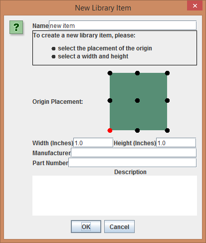
- In Name, enter a unique identifying name for the cutout.
- If you want to change the origin, in Origin Placement click the dot that you want to be the origin. (It will turn red.)
- Note: Using the center as the origin makes it easiest to place objects; you will not need to use the grid because you can center objects on the origin.
- Enter the Height and Width.
- Note: If you are adding cutouts for multiple objects, make each cutout canvas as large as the item that goes into the cutout, not just the hole it goes into, so that you avoid placing objects too close together.
- Click OK.

Saving a custom cutout to the Library from the Face Editor
When you create a cutout of your own on a face, you can save it to the Cutout Library.
- After creating the cutout in the Face Editor, click the Edit button and select all the components of the cutout.
- In the Object Properties panel, first click the Group button, then click the Add to Library button.
- The Edit Properties dialog opens.
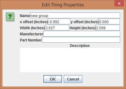
- Enter a new Name for the object.
- You can optionally add x and y offsets, Width, Height, Manufacturer, Part Number, and Description.
- Click OK.
- The object is added to the personal library section of the Cutout Library.
- The object is added to the personal library section of the Cutout Library.

See Also:
Importing DXF files
Two-dimensional DXF files for cutouts, silkscreens, or groups of each can be imported into Protocase Designer directly into your design, or into your Cutout Library. Note that cutouts must be closed loops of continuous lines, and that splines are not supported. Our implementation cannot cover every version of every software tool that makes DXF files. If you have trouble importing a DXF file, please send it to info@protocase.com and state that you cannot import it into Protocase Designer, and if possible let us know what software package it was created in.
How DXF Line Types are converted to Protocase Designer
Note that some DXF line types, upon import, are converted to Construct or Exclusion zones.
| DXF | Protocase Designer |
| Continuous | Construct |
| By Layer | Construct |
| Center | Exclusion |
| CenterX2 | Exclusion |
| Hidden | Construct |
| Dotted | Profile (a boundary that provides you with a point of reference, like a construct does) |
To import a DXF directly into a design
- Load the assembly and select the face you want to add the cutout to.
- In the Face Editor, choose Cutout Library and Fasteners > Place Object From File.
- Browse to the DXF file, select it and click Open.
- If units of measure are not found in the file, you are prompted to select the unit (Inches, MM, or CM).
- The New Library Item dialog opens, with the Keep Default Origin radio button selected and the default origin displayed as a red dot in the graphic.
- To accept the default, click OK. To change the default, select the Assign New Origin radio button, click the dot that you want to be the new origin, then click OK.
- The Face Editor opens with the cutout displayed at the cursor location. Move it to the desired location on the face, and click to place it on the face with its origin at that point.
To import the DXF file into your Cutout Library
- From the 3D View, choose Cutout Library Manager > Open Cutout Manager, or, from the Face Editor, choose Cutout Library and Fasteners > Cutout Library Manager.
- Click Load Item from File.
- Browse to the DXF file, select it and click Open.
- The New Library Item dialog opens, with the Keep Default Origin radio button selected and the default origin displayed as a red dot in the graphic.
- To accept the default, click OK. To change the default, select the Assign New Origin radio button, click the dot that you want to be the new origin, then click OK.
- The cutout is added to your library and is displayed at the bottom of the cutout list.