Difference between revisions of "Cutout Library"
(→Importing DXF files) |
Amacdonald (talk | contribs) (→Contributing a custom cutout to the online library) |
||
| (22 intermediate revisions by the same user not shown) | |||
| Line 1: | Line 1: | ||
| − | == | + | ==Library Manager Overview== |
| − | To get you started quickly in customizing your enclosure design, Protocase Designer includes a built-in | + | To get you started quickly in customizing your enclosure design, Protocase Designer includes a built-in library of common cutouts, graphics, fasteners, hardware and more. You can also use the library to create, edit, delete, organize, and place single or groups of cutouts on your enclosure. All cutouts are in the PDC (Protocase Designer Cutout) format.<br><br> |
Protocase also offers a separate, online cutout library, which provides cutouts in DXF (Drawing Interchange Format, or Drawing Exchange Format) and SLDPRT (SolidWorks Part File) formats. You can download any cutout for free, and contribute custom cutouts of your own. You can also update the local Designer library from the online one. For more information on using the online library or to search it, see '''[[http://www.protocase.com/design/cutout-library/ Protocase online Cutout Library]]'''.<br><br> | Protocase also offers a separate, online cutout library, which provides cutouts in DXF (Drawing Interchange Format, or Drawing Exchange Format) and SLDPRT (SolidWorks Part File) formats. You can download any cutout for free, and contribute custom cutouts of your own. You can also update the local Designer library from the online one. For more information on using the online library or to search it, see '''[[http://www.protocase.com/design/cutout-library/ Protocase online Cutout Library]]'''.<br><br> | ||
The rest of this page contains information on the Designer cutout library, including how to contribute a design (that you have added to your Designer library) to the online library. | The rest of this page contains information on the Designer cutout library, including how to contribute a design (that you have added to your Designer library) to the online library. | ||
| − | ==Opening the | + | ==Opening the Library Manager== |
| − | + | In both the 3D Viewer and the Face Editor, choose the type of object from the Library drop-down menu, then click '''Go'''.<br><br> | |
| − | [[File: | + | [[File:Opening the Library Manager.png|600px]]<br><br> |
| − | The | + | The Library Manager is organized into different categories of items, which are listed on each tab: Cutouts, Graphics, Hardware, Fasteners, Components and Personal. The cutouts you create (or modify) and save are automatically added to the personal library. This prevents the main library of stock cutouts from being changed, and also helps you find your own cutouts more easily. You can add, delete, or edit any item or category in the personal library, but not in the main library. <br><br> |
| − | + | [[File:Opening the Library Manager.png|600px]]<br><br> | |
| + | Click any tab to view its items, which are sorted into sub-folders; Double click the folder to view the items stored within it; click any item to view it along with details such as its name, manufacturer, and part number.<br><br> | ||
| + | [[File:File:Library manager sub-folders.png|600px]]<br><br> | ||
| + | You can also use the search tab to find a specific item you need for your design. Note: You must pre-select the tab that you wish to search within. The search field does not search across all tabs. | ||
| + | [[File:Library manager search field.png|600px]]<br><br> | ||
| − | ==Managing | + | ==Managing Library Manager Items== |
| − | + | <br> | |
| − | When opening the | + | When opening the Library Manager from the 3D View, you can create a copy for edit. This edited copy of the cutout will be saved in your Personal Library.<br> |
| − | + | [[File:Managing cutout library items 3D viewer.png|600px]]<br> | |
| − | + | <br> | |
| − | + | When using the Library Manager from the Face Editor ('''Cutout Library and Fasteners''' > '''Cutout Library'''), you can also: | |
| − | + | :*'''Place Item''': Place the item onto the current face.<br> | |
| − | + | [[File:Managing cutout library items face editor.png|600px]]<br> | |
| − | + | When you click this button the Face Editor opens, and the cursor changes to an image of object footprint. Click in each location on the face where you wish to place the object; when done, press <Esc>.<br><br> | |
| − | + | [[File:Place item from library manager.png|300px]] | |
| − | |||
| − | When | ||
| − | :*'''Place Item''': Place the item onto the current face. When you click this button the Face Editor opens, and the cursor changes to an image of | ||
| − | ==Creating a | + | ==Creating a New Item in Your Personal Library== |
| − | #:In the Library Manager window, click the '''New Item''' button. The New Library Item dialog opens. | + | #:In the Library Manager window, select the Personal tab and click the '''New Item''' button. |
| − | # | + | #:[[File:Create new item from library manager.png|300px]] |
| + | #The New Library Item dialog opens. | ||
| + | #[[File:New library item.png|400px]] | ||
#In '''Name''', enter a unique identifying name for the cutout. | #In '''Name''', enter a unique identifying name for the cutout. | ||
#If you want to change the default origin (shown as a red dot), in '''Origin Placement''' click the dot that you want to be the origin. (It will turn red.) | #If you want to change the default origin (shown as a red dot), in '''Origin Placement''' click the dot that you want to be the origin. (It will turn red.) | ||
#;'''Notes''' | #;'''Notes''' | ||
| − | #*The origin is the origin of the canvas, not just of the cutout on it. | + | #*The origin is the origin of the canvas, not just of the cutout on it. |
#*Using the center as the origin makes it easiest to place objects; you will not need to use the grid because you can center objects on the origin. | #*Using the center as the origin makes it easiest to place objects; you will not need to use the grid because you can center objects on the origin. | ||
#Enter the '''Height''' and '''Width''' of the cutout canvas. This is the area shown in green, on which the cutout is drawn. '''Tip''': Make each cutout canvas as large as the item that goes into the cutout, not just the hole it goes into, so that you can add an '''[[Face_Editor#Using_the_Exclusion_drawing_mode | exclusion zone]]''' that fills the canvas around the cutout to prevent objects from being placed too closely. | #Enter the '''Height''' and '''Width''' of the cutout canvas. This is the area shown in green, on which the cutout is drawn. '''Tip''': Make each cutout canvas as large as the item that goes into the cutout, not just the hole it goes into, so that you can add an '''[[Face_Editor#Using_the_Exclusion_drawing_mode | exclusion zone]]''' that fills the canvas around the cutout to prevent objects from being placed too closely. | ||
| − | # | + | #When you click OK, you will be taken to your object editor, where you will create the object that you need using all of the same tools in the Face Editor. |
| − | #Create | + | #[[File:Create new object in editor.PNG|400px]] |
| + | #When done, click '''Save'''. The custom object you've created is now is added to the '''personal library''' section of the Library Manager.<br><br> | ||
| − | ==Saving | + | ==Saving an object to your Personal Library from the Face Editor== |
| − | When you create a cutout of your own on a face, you can save it to the Cutout Library. | + | When you create a cutout, graphic, masking, exclusion of your own on a face, you can save it to the Cutout Library. |
| − | #After creating the cutout in the Face Editor, click | + | #After creating the cutout in the Face Editor, right-click and select '''Add to Library''' |
| − | #If the cutout consists of more than one object, click | + | [[File:Add cutout to library.png|400px]]<br> |
| − | #Click the '''Add to Library''' | + | #If the cutout consists of more than one object, right-click and select '''Group'''. '''Note''' When grouped, the origin for the group is the origin of the first object created in the group. |
| − | #;[[File: | + | #Click the '''Add to Library''' in the right-hand. The Edit Properties dialog opens. |
| − | #Enter a new '''Name''' for the cutout. You can optionally add ''' | + | #;[[File:Edit new library item.png|300px]]<br> |
| − | #Click '''OK.''' The cutout is added to the | + | #Enter a new '''Name''' for the cutout. You can optionally add '''Manufacturer''', '''Part Number''', '''Link''' and '''Description'''. |
| − | + | #Click '''OK.''' The cutout is added to the Personal tab of the Library Manager.<br> | |
| − | |||
==Changing the origin of an existing cutout== | ==Changing the origin of an existing cutout== | ||
| Line 61: | Line 64: | ||
[[File: change_origin_4.png|200px]]<br><br> | [[File: change_origin_4.png|200px]]<br><br> | ||
| − | ==Contributing a cutout | + | ==Contributing a custom cutout to the online library== |
| − | Once you have added a cutout to your | + | Once you have added a cutout to your Personal library, you can contribute it to the online library as follows: |
| − | #Open the | + | #Open the Library Manager |
| − | #From the ''' | + | #From the '''Personal''' tab, select the cutout you want to contribute. |
| − | #Click the '''Upload | + | #Click the '''Upload''' button. |
| − | #;[[File: | + | #[[File:Upload to online library.png]] |
| + | #The Review Upload dialog opens: | ||
| + | #;[[File:Upload to library information.PNG|400px]] | ||
#Enter the: | #Enter the: | ||
#*'''Category''' (for example, PEMs, Connectors, Decorative, Fans, etc.) | #*'''Category''' (for example, PEMs, Connectors, Decorative, Fans, etc.) | ||
#*'''Sub Category''' (for example, Screws, Nuts, Standoffs, and Studs are all subcategories of PEMs) | #*'''Sub Category''' (for example, Screws, Nuts, Standoffs, and Studs are all subcategories of PEMs) | ||
| − | + | #*If you ''also'' want to contribute a Solidworks file for the same item, click the '''Browse''' button and select the file to contribute. | |
| − | #*If you ''also'' want to contribute a Solidworks file for the same item, click the '''Browse''' button and select the file to contribute. | + | #*Enter your email address (and you can opt to remember that email for future uploads. |
#Click the '''Submit''' button.<br><br> | #Click the '''Submit''' button.<br><br> | ||
| + | #Our Engineering & Design Services team will review your submission. Once it is verified, your cutout will be publicly available in the Cutout tab. | ||
==Importing DXF files== | ==Importing DXF files== | ||
Two-dimensional DXF files for cutouts, graphics, or groups of each can be imported into Protocase Designer directly into your design, or into your Cutout Library. | Two-dimensional DXF files for cutouts, graphics, or groups of each can be imported into Protocase Designer directly into your design, or into your Cutout Library. | ||
| − | To import a dxf it must be an ascii dxf, not a binary dxf. This is usually an option in the dxf export for most software. It has been tested with autodesk version R12 and R14. | + | To import a dxf it must be an ascii dxf, not a binary dxf. This is usually an option in the dxf export for most software. It has been tested with autodesk version R12 and R14, as well as SolidWorks 2018. |
Note that cutouts must be closed loops of continuous lines, and that splines are not supported. (The Protocase laser cuts only lines and circular arcs.) Since our implementation cannot cover every version of every software tool that makes DXF files, if you have trouble importing a DXF file, please send it to designer@protocase.com and state that you cannot import it into Protocase Designer, and if possible let us know what software package it was created in.<br><br> | Note that cutouts must be closed loops of continuous lines, and that splines are not supported. (The Protocase laser cuts only lines and circular arcs.) Since our implementation cannot cover every version of every software tool that makes DXF files, if you have trouble importing a DXF file, please send it to designer@protocase.com and state that you cannot import it into Protocase Designer, and if possible let us know what software package it was created in.<br><br> | ||
| Line 84: | Line 90: | ||
Some DXF line types, upon import, are converted to Construct or Exclusion zones. | Some DXF line types, upon import, are converted to Construct or Exclusion zones. | ||
| + | |||
| + | The Exclusion object type is used to mark areas where other objects (except text and graphics) cannot be added. Constructs, on the other hand, add a design or other reference (including a note) to any part of the design. Construct objects never affect production, or impede where objects can be placed. | ||
| + | |||
{| | {| | ||
|''DXF''||| ''Protocase Designer'' | |''DXF''||| ''Protocase Designer'' | ||
| Line 105: | Line 114: | ||
|| Profile (a boundary that provides you with a point of reference, like a construct does) | || Profile (a boundary that provides you with a point of reference, like a construct does) | ||
|} | |} | ||
| + | |||
| + | Read more about constructs [https://www.protocasedesigner.com/wiki/index.php?title=Face_Editor#Using_the_Construct_object_type/ here] and exclusions [https://www.protocasedesigner.com/wiki/index.php?title=Face_Editor#Using_the_Exclusion_object_type/ here]. | ||
| Line 113: | Line 124: | ||
#Browse to the DXF file, select it and click '''Open'''. | #Browse to the DXF file, select it and click '''Open'''. | ||
#:If units of measure are not found in the file, you are prompted to select the unit ('''Inches''', '''MM''', or '''CM'''). | #:If units of measure are not found in the file, you are prompted to select the unit ('''Inches''', '''MM''', or '''CM'''). | ||
| − | #:The New Library Item dialog opens, with the '''Keep Default Origin''' radio button selected | + | #:The New Library Item dialog opens, with the '''Keep Default Origin''' radio button selected. |
#To accept the default, click '''OK.''' To change the default, select the '''Assign New Origin''' radio button, click the dot that you want to be the new origin, then click '''OK.''' | #To accept the default, click '''OK.''' To change the default, select the '''Assign New Origin''' radio button, click the dot that you want to be the new origin, then click '''OK.''' | ||
#:The Face Editor opens with the cutout displayed at the cursor location. Move it to the desired location on the face, and click to place it on the face with its origin at that point. | #:The Face Editor opens with the cutout displayed at the cursor location. Move it to the desired location on the face, and click to place it on the face with its origin at that point. | ||
| Line 123: | Line 134: | ||
#Click '''Load Item from File'''. | #Click '''Load Item from File'''. | ||
#Browse to the DXF file, select it and click '''Open'''. | #Browse to the DXF file, select it and click '''Open'''. | ||
| − | #:The New Library Item dialog opens, with the '''Keep Default Origin''' radio button selected | + | #:The New Library Item dialog opens, with the '''Keep Default Origin''' radio button selected. |
#To accept the default, click '''OK.''' To change the default, select the '''Assign New Origin''' radio button, click the dot that you want to be the new origin, then click '''OK.''' | #To accept the default, click '''OK.''' To change the default, select the '''Assign New Origin''' radio button, click the dot that you want to be the new origin, then click '''OK.''' | ||
#:The cutout is added to your library and is displayed at the bottom of the cutout list. | #:The cutout is added to your library and is displayed at the bottom of the cutout list. | ||
Latest revision as of 13:59, 5 May 2023
Contents
- 1 Library Manager Overview
- 2 Opening the Library Manager
- 3 Managing Library Manager Items
- 4 Creating a New Item in Your Personal Library
- 5 Saving an object to your Personal Library from the Face Editor
- 6 Changing the origin of an existing cutout
- 7 Contributing a custom cutout to the online library
- 8 Importing DXF files
Library Manager Overview
To get you started quickly in customizing your enclosure design, Protocase Designer includes a built-in library of common cutouts, graphics, fasteners, hardware and more. You can also use the library to create, edit, delete, organize, and place single or groups of cutouts on your enclosure. All cutouts are in the PDC (Protocase Designer Cutout) format.
Protocase also offers a separate, online cutout library, which provides cutouts in DXF (Drawing Interchange Format, or Drawing Exchange Format) and SLDPRT (SolidWorks Part File) formats. You can download any cutout for free, and contribute custom cutouts of your own. You can also update the local Designer library from the online one. For more information on using the online library or to search it, see [Protocase online Cutout Library].
The rest of this page contains information on the Designer cutout library, including how to contribute a design (that you have added to your Designer library) to the online library.
Opening the Library Manager
In both the 3D Viewer and the Face Editor, choose the type of object from the Library drop-down menu, then click Go.

The Library Manager is organized into different categories of items, which are listed on each tab: Cutouts, Graphics, Hardware, Fasteners, Components and Personal. The cutouts you create (or modify) and save are automatically added to the personal library. This prevents the main library of stock cutouts from being changed, and also helps you find your own cutouts more easily. You can add, delete, or edit any item or category in the personal library, but not in the main library.
Click any tab to view its items, which are sorted into sub-folders; Double click the folder to view the items stored within it; click any item to view it along with details such as its name, manufacturer, and part number.
600px
You can also use the search tab to find a specific item you need for your design. Note: You must pre-select the tab that you wish to search within. The search field does not search across all tabs.

Managing Library Manager Items
When opening the Library Manager from the 3D View, you can create a copy for edit. This edited copy of the cutout will be saved in your Personal Library.

When using the Library Manager from the Face Editor (Cutout Library and Fasteners > Cutout Library), you can also:
- Place Item: Place the item onto the current face.
- Place Item: Place the item onto the current face.

When you click this button the Face Editor opens, and the cursor changes to an image of object footprint. Click in each location on the face where you wish to place the object; when done, press <Esc>.

Creating a New Item in Your Personal Library
- In the Library Manager window, select the Personal tab and click the New Item button.
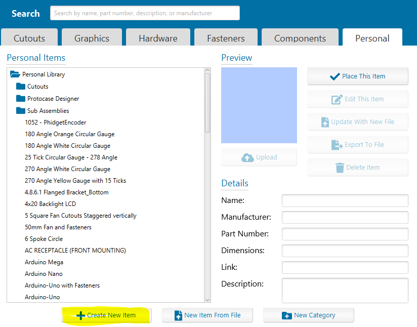
- The New Library Item dialog opens.
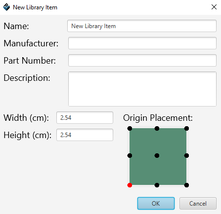
- In Name, enter a unique identifying name for the cutout.
- If you want to change the default origin (shown as a red dot), in Origin Placement click the dot that you want to be the origin. (It will turn red.)
- Notes
- The origin is the origin of the canvas, not just of the cutout on it.
- Using the center as the origin makes it easiest to place objects; you will not need to use the grid because you can center objects on the origin.
- Enter the Height and Width of the cutout canvas. This is the area shown in green, on which the cutout is drawn. Tip: Make each cutout canvas as large as the item that goes into the cutout, not just the hole it goes into, so that you can add an exclusion zone that fills the canvas around the cutout to prevent objects from being placed too closely.
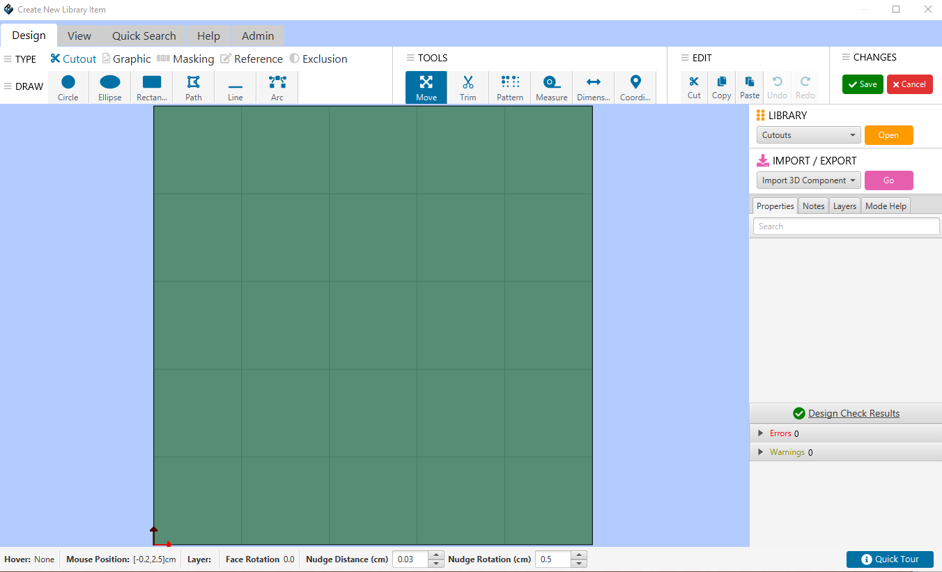
- When you click OK, you will be taken to your object editor, where you will create the object that you need using all of the same tools in the Face Editor.
- When done, click Save. The custom object you've created is now is added to the personal library section of the Library Manager.


Saving an object to your Personal Library from the Face Editor
When you create a cutout, graphic, masking, exclusion of your own on a face, you can save it to the Cutout Library.
- After creating the cutout in the Face Editor, right-click and select Add to Library

- If the cutout consists of more than one object, right-click and select Group. Note When grouped, the origin for the group is the origin of the first object created in the group.
- Click the Add to Library in the right-hand. The Edit Properties dialog opens.
- Enter a new Name for the cutout. You can optionally add Manufacturer, Part Number, Link and Description.
- Click OK. The cutout is added to the Personal tab of the Library Manager.

Changing the origin of an existing cutout
The best use of this procedure is after you group and/or merge items in the Face Editor and save them as a cutout, because Designer does not have control over where the origin ends up, and you might want to change the origin to make it more useful for placement.
- From the 3D View window, choose Cutout Library Manager > Open Cutout Manager, browse to find the item, and click to select it.
- Click the Edit Item button. The cutout is displayed in the Cutout Editor, with the origin shown as a blue circle with two axis arrows. In this example, we will move the origin in the Large Rackmount Handle from the center to the lower left.
- Click the origin and hold down the mouse button while you drag the cutout (and canvas) so that the origin is in the desired location. If you need to place the origin at an exact position, use the coordinates in the lower left corner of the screen as your reference while you drag the cutout. (The cutout moves around the origin, so you might need to pan and/or zoom to keep the image squarely in view.)
- Click the ‘’’Accept and Close’’’ button.


Note In the above example, the origin has been placed in the lower left corner of the canvas, not of the slot cutout itself. Be sure to account for this, if necessary, when placing it on a face. Here is another example of the difference:
Cutout moved so that origin is in center of canvas:

Cutout moved so that origin is in center of cutout:

Contributing a custom cutout to the online library
Once you have added a cutout to your Personal library, you can contribute it to the online library as follows:
- Open the Library Manager
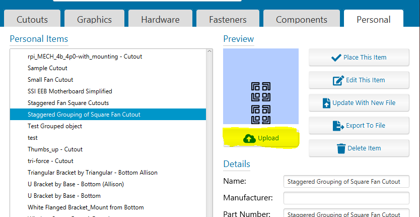
- From the Personal tab, select the cutout you want to contribute.
- Click the Upload button.
- The Review Upload dialog opens:
- Enter the:
- Category (for example, PEMs, Connectors, Decorative, Fans, etc.)
- Sub Category (for example, Screws, Nuts, Standoffs, and Studs are all subcategories of PEMs)
- If you also want to contribute a Solidworks file for the same item, click the Browse button and select the file to contribute.
- Enter your email address (and you can opt to remember that email for future uploads.
- Click the Submit button.
- Our Engineering & Design Services team will review your submission. Once it is verified, your cutout will be publicly available in the Cutout tab.


Importing DXF files
Two-dimensional DXF files for cutouts, graphics, or groups of each can be imported into Protocase Designer directly into your design, or into your Cutout Library.
To import a dxf it must be an ascii dxf, not a binary dxf. This is usually an option in the dxf export for most software. It has been tested with autodesk version R12 and R14, as well as SolidWorks 2018.
Note that cutouts must be closed loops of continuous lines, and that splines are not supported. (The Protocase laser cuts only lines and circular arcs.) Since our implementation cannot cover every version of every software tool that makes DXF files, if you have trouble importing a DXF file, please send it to designer@protocase.com and state that you cannot import it into Protocase Designer, and if possible let us know what software package it was created in.
How DXF Line Types are converted to Protocase Designer
Some DXF line types, upon import, are converted to Construct or Exclusion zones.
The Exclusion object type is used to mark areas where other objects (except text and graphics) cannot be added. Constructs, on the other hand, add a design or other reference (including a note) to any part of the design. Construct objects never affect production, or impede where objects can be placed.
| DXF | Protocase Designer |
| Continuous | Construct |
| By Layer | Construct |
| Center | Exclusion |
| CenterX2 | Exclusion |
| Hidden | Construct |
| Dotted | Profile (a boundary that provides you with a point of reference, like a construct does) |
Read more about constructs here and exclusions here.
To import a DXF file into a design
- If the DXF is that of a circuit board, first remove everything from the DXF file except the mounting holes and the board outline, and change the board outline to the Hidden or CenterX2 line type. (As noted above, in Designer the Hidden line type becomes a Construct, and the CENTERX2 line type becomes an Exclusion.)
- Load the assembly and select the face you want to add the cutout to.
- In the Face Editor, choose Cutout Library and Fasteners > Place Object From File.
- Browse to the DXF file, select it and click Open.
- If units of measure are not found in the file, you are prompted to select the unit (Inches, MM, or CM).
- The New Library Item dialog opens, with the Keep Default Origin radio button selected.
- To accept the default, click OK. To change the default, select the Assign New Origin radio button, click the dot that you want to be the new origin, then click OK.
- The Face Editor opens with the cutout displayed at the cursor location. Move it to the desired location on the face, and click to place it on the face with its origin at that point.
To import a DXF file into your Cutout Library
- If the DXF is that of a circuit board, first remove everything from the DXF file except the mounting holes and the board outline, and change the board outline to the Hidden or CenterX2 line type. (As noted above, in Designer the Hidden line type becomes a Construct, and the CenterX2 line type becomes an Exclusion.)
- From the 3D View, choose Cutout Library Manager > Open Cutout Manager, or, from the Face Editor, choose Cutout Library and Fasteners > Cutout Library Manager.
- Click Load Item from File.
- Browse to the DXF file, select it and click Open.
- The New Library Item dialog opens, with the Keep Default Origin radio button selected.
- To accept the default, click OK. To change the default, select the Assign New Origin radio button, click the dot that you want to be the new origin, then click OK.
- The cutout is added to your library and is displayed at the bottom of the cutout list.