Difference between revisions of "Creating an enclosure to mount a PCB"
m (→Add PCB and power supply cutouts to rear panel) |
m |
||
| Line 83: | Line 83: | ||
{{Procedure| | {{Procedure| | ||
#On the '''Cutout Library and Fasteners''' menu, point to '''Fans''', '''General''', then click '''60mm'''. | #On the '''Cutout Library and Fasteners''' menu, point to '''Fans''', '''General''', then click '''60mm'''. | ||
| − | #Click on the face to place the fan cutout at the approximate mounting location.<br><br>[[File:window-faceeditor-rackmount-rear-fan-placing.png|600px|thumb|center|Face Editor | + | #Click on the face to place the fan cutout at the approximate mounting location.<br><br>[[File:window-faceeditor-rackmount-rear-fan-placing.png|600px|thumb|center|Face Editor window: placing fan cutout]]<br> |
#On the '''Drawing''' toolbar, select the '''Edit''' tool. [[File:tool-edit.png|40px|bottom]] | #On the '''Drawing''' toolbar, select the '''Edit''' tool. [[File:tool-edit.png|40px|bottom]] | ||
#Select the fan cutout and update the origin as follows: | #Select the fan cutout and update the origin as follows: | ||
#*Fan cutout | #*Fan cutout | ||
#:Origin(X): 7.5 | #:Origin(X): 7.5 | ||
| − | #:Origin(Y): 1.5<br><br>[[File:window-faceeditor-rackmount-rear-fan-origin.png|600px|thumb|center|Face Editor | + | #:Origin(Y): 1.5<br><br>[[File:window-faceeditor-rackmount-rear-fan-origin.png|600px|thumb|center|Face Editor window: rack mount with rectangle cutouts and fan cutout]]<br> |
#On the '''Standard''' toolbar, click '''Accept & Close'''. [[File:button-acceptclose.png|40px|bottom]] | #On the '''Standard''' toolbar, click '''Accept & Close'''. [[File:button-acceptclose.png|40px|bottom]] | ||
}} | }} | ||
| Line 96: | Line 96: | ||
#On the '''Standard''' toolbar, click '''Edit Face''' [[File:button-editface.png|40px|bottom]], then click the chassis (bottom) of the enclosure. The '''Face Editor''' window opens. | #On the '''Standard''' toolbar, click '''Edit Face''' [[File:button-editface.png|40px|bottom]], then click the chassis (bottom) of the enclosure. The '''Face Editor''' window opens. | ||
#On the '''Standard''' toolbar, click '''Inside''' [[File:button-inside.png|60px|middle]] to change the view to the inside of the chassis. | #On the '''Standard''' toolbar, click '''Inside''' [[File:button-inside.png|60px|middle]] to change the view to the inside of the chassis. | ||
| − | #On the '''Cutout Library and Fasteners''' menu, click '''Place Self Clinching Fasteners'''.<br><br>[[File:dialogbox-pem-studs-440-500.png|300px|thumb|center|Self Clinching Fastener dialog | + | #On the '''Cutout Library and Fasteners''' menu, click '''Place Self Clinching Fasteners'''.<br><br>[[File:dialogbox-pem-studs-440-500.png|300px|thumb|center|Self Clinching Fastener dialog box: selecting studs, 4-40 x .500" long]] |
#Select Studs, 4-40 x .500 long and click '''Place PEM'''. | #Select Studs, 4-40 x .500 long and click '''Place PEM'''. | ||
| − | #Click on the face to place two studs at the approximate mounting location for the power supply.<br><br>[[File:window-faceeditor-rackmount-chassis-studs.png|600px|thumb|center|Face Editor | + | #Click on the face to place two studs at the approximate mounting location for the power supply.<br><br>[[File:window-faceeditor-rackmount-chassis-studs.png|600px|thumb|center|Face Editor Window: placing studs, 4-40 x .500" long]] |
| − | #On the '''Cutout Library and Fasteners''' menu, click '''Place Self Clinching Fasteners'''.<br><br>[[File:dialogbox-pem-standoffs-440-375.png|300px|thumb|center|Self Clinching Fastener dialog | + | #On the '''Cutout Library and Fasteners''' menu, click '''Place Self Clinching Fasteners'''.<br><br>[[File:dialogbox-pem-standoffs-440-375.png|300px|thumb|center|Self Clinching Fastener dialog box: selecting standoffs, 4-40 x .375" long]] |
#Select Standoffs, 4-40 x .375" long and click '''Place PEM'''. | #Select Standoffs, 4-40 x .375" long and click '''Place PEM'''. | ||
| − | #Click on the face to place four standoffs at the approximate mounting location for the PCB (on the right).<br><br>[[File:window-faceeditor-rackmount-chassis-standoffs.png|600px|thumb|center|Face Editor | + | #Click on the face to place four standoffs at the approximate mounting location for the PCB (on the right).<br><br>[[File:window-faceeditor-rackmount-chassis-standoffs.png|600px|thumb|center|Face Editor window: placing standoffs, 4-40 x .375" long]] |
#On the '''Drawing''' toolbar, select the '''Edit''' tool. [[File:tool-edit.png|40px|bottom]] | #On the '''Drawing''' toolbar, select the '''Edit''' tool. [[File:tool-edit.png|40px|bottom]] | ||
#Select each standoff and stud and update their origins as follows: | #Select each standoff and stud and update their origins as follows: | ||
| Line 121: | Line 121: | ||
#*Standoff 4 | #*Standoff 4 | ||
#:Origin(X): 15.65 | #:Origin(X): 15.65 | ||
| − | #:Origin(Y): 8<br><br>[[File:window-faceeditor-rackmount-chassis-pems-origin.png|600px|thumb|center|Face Editor | + | #:Origin(Y): 8<br><br>[[File:window-faceeditor-rackmount-chassis-pems-origin.png|600px|thumb|center|Face Editor Window: studs and standoffs placed in proper locations]] |
| − | #On the '''Drawing toolbar''', click '''Accept & Close'''. [[File:button-acceptclose.png|40px|bottom]]<br><br>[[File:window-main-rackmount-pems.png|600px|thumb|center|Main | + | #On the '''Drawing toolbar''', click '''Accept & Close'''. [[File:button-acceptclose.png|40px|bottom]]<br><br>[[File:window-main-rackmount-pems.png|600px|thumb|center|Main window: rack mount with studs and standoffs added]] |
}} | }} | ||
You can now customize your enclosure further by adding additional cutouts, silkscreen, and hardware to the other faces and then request an instant quote. | You can now customize your enclosure further by adding additional cutouts, silkscreen, and hardware to the other faces and then request an instant quote. | ||
Revision as of 17:10, 29 April 2014
One of the most common uses for Protocase Designer is to design a custom enclosure to mount a PCB (Printed Circuit Board) and associated components. This tutorial will guide you through the process of creating a custom rackmount enclosure to mount a mini-ITX PCB using self-clinching fasteners, and create cutouts for the PCB, power supply, and fan.
Contents
- 1 Select components to mount in enclosure
- 2 Determine mounting specifications for components
- 3 Determine mounting locations for components
- 4 Create enclosure from template
- 5 Add PCB and power supply cutouts to rear panel
- 6 Add built-in fan cutout to rear panel
- 7 Add self-clinching fasteners to chassis
Select components to mount in enclosure
Determine mounting specifications for components
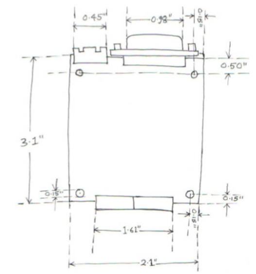
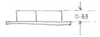
The figures below are rough sketches of the example components with their measurements. All dimensions (given in inches) are measured using mechanical calipers. Template:Procedure
- Note: Mounting dimensions are not needed for the 60mm fan, since a built-in cutout for the fan will be used.
- Note: It is important to properly understand how to mount each component, including any required clearances.
Determine mounting locations for components
- Note: Dimensions are always measured from the absolute origin shown on the OUTSIDE of the base of the enclosure, and therefore you must factor in the thickness of the enclosure.
Tips on positioning components and cutouts
- If the board needs to be mounted close to a wall of the enclosure, do not place the mounting holes too close to the edge of the board. The example below shows two boards, each with two mounting holes and a DB-9 panel mount connector. On the board on the left (A), the connector holes are located 0.150” from the edge of the board. On the board on the right (B), the mounting holes are placed well back from the edge of the board. The difficulty with the board on the left is the fact that since it has a DB-9 panel connector, the board must be placed sufficiently close to the rear panel of the enclosure so as to allow the DB-9 to pass through the enclosure rear panel. In order to get the board close enough to the vertical side of the enclosure to accommodate the DB-9 connector, the required mounting hardware for the board must be installed so close to the edge of the enclosure that it will interfere with the enclosure bend radius, making it difficult to manufacture, if not impossible. With the board on the right, there is no problem because the mounting holes are far enough back to prevent any interference. A good rule of thumb is to leave at least 0.375" between the centre of the mounting hole and the edge of the board.

- Always mount panel mount connectors so that they are not flush with the edge of the board. In the example below, the board on the left (A) has the connector mounted so close to the edge of the board that the board will have to be mounted with its edge just touching the vertical side of the enclosure so that it can accommodate the connector. Allowing for manufacturing tolerances means that the board might be jammed into position when it is mounted, thus inducing stress on the board and compromising its electrical integrity. The board on the right (B) is done properly.

- When determining the locations for the connectors, it is essential to find the height of the cutouts by counting the height of the standoff, board, and gap between connector, as shown in the following example for a DB-9 cutout.
- The top view, showing the important dimensions including the mounting holes, the cutout, and the connectors:
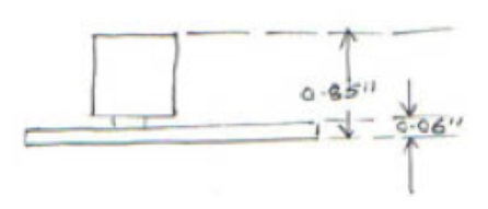
- The height of the connector:
- The height of 0.85", to which you would add a height clearance of 0.15". Thus the total height would be 1" (= 0.85" + 0.15"):
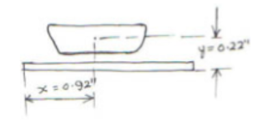
- The dimension of the DB-9 cutout, which helps you locate the center point on the board:


Create enclosure from template
Add PCB and power supply cutouts to rear panel
This enclosure requires two rectangular cutouts on the rear panel to accommodate the mini-ITX PCB and power supply. Template:Procedure
Add built-in fan cutout to rear panel
Protocase Designer® offers a library of cutouts for common components including fans of various sizes. Template:Procedure
Add self-clinching fasteners to chassis
Template:Procedure You can now customize your enclosure further by adding additional cutouts, silkscreen, and hardware to the other faces and then request an instant quote.