Difference between revisions of "Creating a custom cutout for a connector"
From Protocase Designer Documentation
(→Method 2: Creating objects in the Cutout Editor) |
(→Method 2: Creating objects in the Cutout Editor) |
||
| Line 30: | Line 30: | ||
#(Optional) Enter the Manufacturer, Part Number and/or Description. | #(Optional) Enter the Manufacturer, Part Number and/or Description. | ||
#Create your cutouts using the Drawing tools. You can also include silkscreen text and images.<br><br>[[File:window-cutouteditor-connector.png|500px|thumb|center|Creating a custom cutout in the Cutout Editor]]<br> | #Create your cutouts using the Drawing tools. You can also include silkscreen text and images.<br><br>[[File:window-cutouteditor-connector.png|500px|thumb|center|Creating a custom cutout in the Cutout Editor]]<br> | ||
| − | #On the ''' | + | #On the '''Standard''' toolbar, click '''Accept & Close'''. [[File:button-acceptclose.png|40px|bottom]]<br>Your custom cutout will now appear at the bottom of the Cutout Library item list. |
}} | }} | ||
Revision as of 17:16, 19 September 2012
Contents
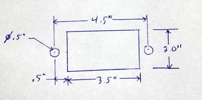
Determine mounting specifications
- Determine the mounting specifications (mounting hole and cutout dimensions) for the connector.
Draw Cutouts
There are two methods to create a custom cutout in the Cutout Library.
- Method 1—Grouping objects and adding to the Cutout Library
- Method 2—Creating objects directly in the Cutout Editor
