Difference between revisions of "Creating a custom cutout for a connector"
From Protocase Designer Documentation
m (→Method 2: Creating objects in the Cutout Editor) |
m |
||
| Line 9: | Line 9: | ||
====Method 1: Grouping objects and adding to the Cutout Library==== | ====Method 1: Grouping objects and adding to the Cutout Library==== | ||
{{Procedure| | {{Procedure| | ||
| − | #On the 3D View toolbar, click '''Edit Face''' [[File:button-editface.png|40px|bottom]], then click a face to edit | + | #On the 3D View toolbar, click '''Edit Face''' [[File:button-editface.png|40px|bottom]], then click a face to edit. |
| − | #In the '''Face Editor''' window, create the cutouts required to mount the connector (such as port and mounting screw cutouts). Use the '''Grid''' or '''Measure''' tool to accurately place each cutout.<br><br>[[File:window-faceeditor-ushape-customcutout.png|500px|thumb|center|Several cutouts created to mount a connector]]<br> | + | #In the '''Face Editor''' window that opens, create the cutouts required to mount the connector (such as port and mounting screw cutouts). Use the '''Grid''' or '''Measure''' tool to accurately place each cutout.<br><br>[[File:window-faceeditor-ushape-customcutout.png|500px|thumb|center|Several cutouts created to mount a connector]]<br> |
#Select all the objects to include in your custom cutout. | #Select all the objects to include in your custom cutout. | ||
| − | #On the '''Properties''' panel, click '''Group'''. A bounding box | + | #On the '''Properties''' panel, click '''Group'''. A bounding box is drawn around the objects and controls are added to the '''Properties''' panel for the group. The origin for the new group is based on the origin of the first object created in the group.<br><br>[[File:window-faceeditor-ushape-customcutout-group.png|500px|thumb|center|Several cutouts selected and grouped]]<br> |
#On the '''Properties''' panel, click '''Add to Library'''. A dialog box opens.<br><br>[[File:dialogbox-addtolibrary.png|600px|thumb|center|Add To Library Dialog Box]]<br> | #On the '''Properties''' panel, click '''Add to Library'''. A dialog box opens.<br><br>[[File:dialogbox-addtolibrary.png|600px|thumb|center|Add To Library Dialog Box]]<br> | ||
#Enter a name for the group. | #Enter a name for the group. | ||
Revision as of 16:52, 23 October 2013
Contents
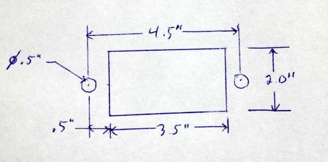
Determine mounting specifications
- Determine the mounting specifications (mounting hole and cutout dimensions) for the connector.
Draw Cutouts
There are two methods to create a custom cutout in the Cutout Library.
- Method 1—Grouping objects and adding to the Cutout Library
- Method 2—Creating objects directly in the Cutout Editor
