Difference between revisions of "Creating a custom cutout for a connector"
From Protocase Designer Documentation
(→Method 2: Creating objects in the Cutout Editor) |
m (→Method 1: Grouping objects and adding to the Cutout Library) |
||
| Line 9: | Line 9: | ||
====Method 1: Grouping objects and adding to the Cutout Library==== | ====Method 1: Grouping objects and adding to the Cutout Library==== | ||
{{Procedure| | {{Procedure| | ||
| − | #On the | + | #On the 3D View toolbar, click '''Edit Face''' [[File:button-editface.png|40px|bottom]], then click a face to edit. The '''Face Editor''' window opens. |
#In the '''Face Editor''' window, create the cutouts required to mount the connector (such as port and mounting screw cutouts). Use the '''Grid''' or '''Measure''' tool to accurately place each cutout.<br><br>[[File:window-faceeditor-ushape-customcutout.png|500px|thumb|center|Several cutouts created to mount a connector]]<br> | #In the '''Face Editor''' window, create the cutouts required to mount the connector (such as port and mounting screw cutouts). Use the '''Grid''' or '''Measure''' tool to accurately place each cutout.<br><br>[[File:window-faceeditor-ushape-customcutout.png|500px|thumb|center|Several cutouts created to mount a connector]]<br> | ||
#Select all the objects to include in your custom cutout. | #Select all the objects to include in your custom cutout. | ||
| Line 15: | Line 15: | ||
#On the '''Properties''' panel, click '''Add to Library'''. A dialog box opens.<br><br>[[File:dialogbox-addtolibrary.png|600px|thumb|center|Add To Library Dialog Box]]<br> | #On the '''Properties''' panel, click '''Add to Library'''. A dialog box opens.<br><br>[[File:dialogbox-addtolibrary.png|600px|thumb|center|Add To Library Dialog Box]]<br> | ||
#Enter a name for the group. | #Enter a name for the group. | ||
| − | #Leave the x and y offset values as | + | #Leave the x and y offset values as is. The x, y offset defines the position of the bounding box corner relative to the group origin. The width and height define the bounding box size. |
| − | #(Optional) Enter the Manufacturer, Part Number and/or Description. | + | #(Optional) Enter the '''Manufacturer''', '''Part Number''' and/or '''Description'''. |
| − | #Click '''OK'''. Your custom cutout will now | + | #Click '''OK'''. Your custom cutout will now be included in the Cutout Library and the '''Cutout Library and Fasteners''' menu. |
}} | }} | ||
Revision as of 16:47, 23 October 2013
Contents
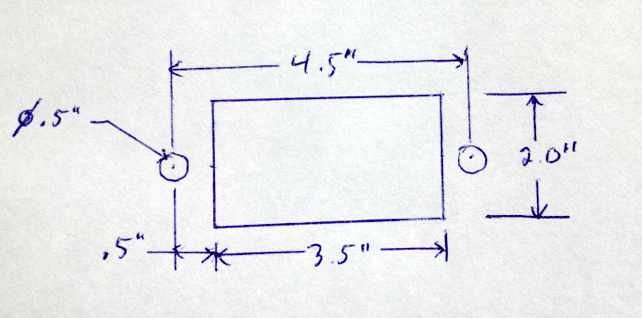
Determine mounting specifications
- Determine the mounting specifications (mounting hole and cutout dimensions) for the connector.
Draw Cutouts
There are two methods to create a custom cutout in the Cutout Library.
- Method 1—Grouping objects and adding to the Cutout Library
- Method 2—Creating objects directly in the Cutout Editor
