Difference between revisions of "Creating a custom cutout for a connector"
From Protocase Designer Documentation
m (→Method 2: Creating objects in the Cutout Editor) |
m |
||
| Line 1: | Line 1: | ||
==Determine mounting specifications== | ==Determine mounting specifications== | ||
| − | #Determine the mounting specifications (mounting hole and cutout dimensions) for the connector. | + | #Determine the mounting specifications (mounting hole and cutout dimensions) for the connector. |
| + | #:[[File:sketch-customconnector.png|400px]] | ||
| − | ==Draw | + | ==Draw cutouts== |
| − | + | You can group objects and add them as a single cutout to the Cutout Library, or create objects directly in the Cutout Editor.<br><br> | |
| − | |||
| − | |||
| − | + | '''''Grouping objects and adding them to the Cutout Library''' | |
| − | + | #On the 3D View toolbar, click '''Edit Face''' [[File:button-editface.png|20px|bottom]], then click a face to edit. | |
| − | #On the 3D View toolbar, click '''Edit Face''' [[File:button-editface.png| | + | #In the '''Face Editor''' window that opens, create the cutouts required to mount the connector (such as port and mounting screw cutouts). Use the '''Grid''', '''Alignment''', and/or '''Measure''' tools to accurately place each cutout. |
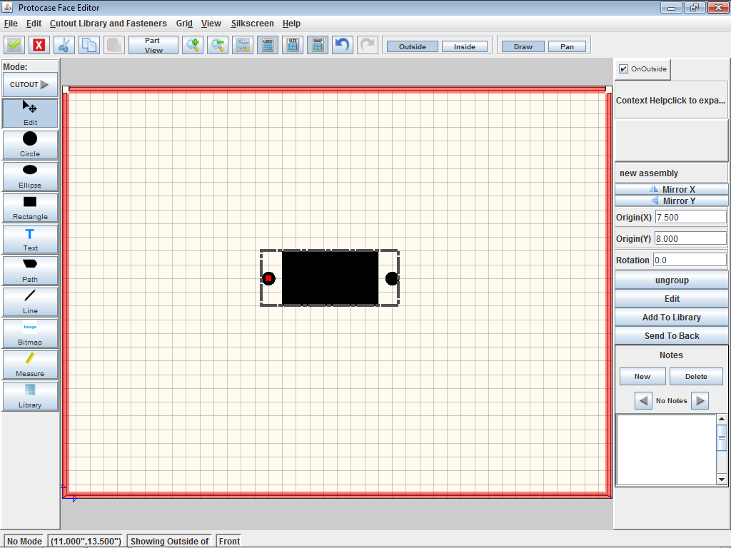
| − | #In the '''Face Editor''' window that opens, create the cutouts required to mount the connector (such as port and mounting screw cutouts). Use the '''Grid''' or '''Measure''' | + | #:[[File:window-faceeditor-ushape-customcutout.png|500px]] |
| − | # | + | #Click the '''Edit''' tool and select all the objects to be included in the custom cutout. |
| − | #On the '''Properties''' panel, click '''Group'''. | + | #On the '''Properties''' panel, click '''Group'''. |
| − | #On the '''Properties''' panel, click '''Add to Library'''. | + | #:A bounding box is drawn around the group, and the Properties panel displays controls for the group. |
| + | #:'''Note''' The origin for the new group is based on the origin of the first object created in the group. | ||
| + | #:[[File:window-faceeditor-ushape-customcutout-group.png|500px]] | ||
| + | #On the '''Properties''' panel, click '''Add to Library'''. The Edit Properties dialog opens. | ||
| + | #:[[File:dialogbox-addtolibrary.png|300px]]<br> | ||
#Enter a name for the group. | #Enter a name for the group. | ||
| − | #Leave the x and y offset values as | + | #Leave the '''x offset''' and '''y offset''' values as they are. These offsets define the position of the bounding box corner relative to the group origin. The '''Width''' and '''Height''' define the size of the bounding box. |
#(Optional) Enter the '''Manufacturer''', '''Part Number''' and/or '''Description'''. | #(Optional) Enter the '''Manufacturer''', '''Part Number''' and/or '''Description'''. | ||
| − | #Click '''OK'''. | + | #Click '''OK'''. |
| − | + | #:The custom cutout is now included in the Cutout Library and the '''Cutout Library and Fasteners''' menu.<br><br> | |
| − | + | '''''To create objects in the Cutout Editor''''' | |
| − | + | #On the 3D View toolbar, click '''Edit Face''' [[File:button-editface.png|20px|bottom]], then click a face to edit. The Face Editor window opens. | |
| − | #On the 3D View toolbar, click '''Edit Face''' [[File:button-editface.png| | + | #On the '''Cutout Library and Fasteners''' menu, click '''Cutout Library'''. The '''Library Manager''' dialog opens. |
| − | #On the '''Cutout Library and Fasteners''' menu, click '''Cutout Library'''. The '''Library Manager''' dialog opens. | + | #:[[File:window-cutoutlibrary.png|500px]] |
| − | #Click '''New Item'''. | + | #Click '''New Item'''. The New Item dialog opens. |
| + | #:[[File:dialogbox-cutoutlibrary-newitem.png|400px]] | ||
#Enter a name for the cutout. | #Enter a name for the cutout. | ||
| − | #Enter the x and y offset values to position the bottom left corner of the bounding box relative to the origin. Entering an x value half of the Width and a y value half of the Height will place the origin in the centre of the bounding box. | + | #Enter the x and y offset values to position the bottom left corner of the bounding box relative to the origin. |
| − | #Enter the Width and Height of the bounding box for your cutout. All your cutouts should fit within this bounding box area. | + | #:Entering an x value half of the '''Width''' and a y value half of the '''Height''' will place the origin in the centre of the bounding box. |
| + | #Enter the '''Width''' and '''Height''' of the bounding box for your cutout. All your cutouts should fit within this bounding box area. | ||
#(Optional) Enter the '''Manufacturer''', '''Part Number''' and/or '''Description'''. | #(Optional) Enter the '''Manufacturer''', '''Part Number''' and/or '''Description'''. | ||
| − | #Create your cutouts using the drawing tools | + | #Create your cutouts using the drawing tools, which include printed or silkscreened text and images. |
| − | #Click '''Accept & Close'''. [[File:button-acceptclose.png| | + | #:[[File:window-cutouteditor-connector.png|500px]] |
| − | + | #Click '''Accept & Close'''. [[File:button-acceptclose.png|20px|bottom]] | |
| + | #:The custom cutout is added to the bottom of the Cutout Library > Personal Items list. | ||
Revision as of 14:27, 15 September 2015
Determine mounting specifications
- Determine the mounting specifications (mounting hole and cutout dimensions) for the connector.

Draw cutouts
You can group objects and add them as a single cutout to the Cutout Library, or create objects directly in the Cutout Editor.
Grouping objects and adding them to the Cutout Library
- On the 3D View toolbar, click Edit Face
 , then click a face to edit.
 - In the Face Editor window that opens, create the cutouts required to mount the connector (such as port and mounting screw cutouts). Use the Grid, Alignment, and/or Measure tools to accurately place each cutout.
- Click the Edit tool and select all the objects to be included in the custom cutout.
- On the Properties panel, click Group.
- A bounding box is drawn around the group, and the Properties panel displays controls for the group.
- Note The origin for the new group is based on the origin of the first object created in the group.
- On the Properties panel, click Add to Library. The Edit Properties dialog opens.
- Enter a name for the group.
- Leave the x offset and y offset values as they are. These offsets define the position of the bounding box corner relative to the group origin. The Width and Height define the size of the bounding box.
- (Optional) Enter the Manufacturer, Part Number and/or Description.
- Click OK.
- The custom cutout is now included in the Cutout Library and the Cutout Library and Fasteners menu.
- The custom cutout is now included in the Cutout Library and the Cutout Library and Fasteners menu.


To create objects in the Cutout Editor
- On the 3D View toolbar, click Edit Face , then click a face to edit. The Face Editor window opens.
- On the Cutout Library and Fasteners menu, click Cutout Library. The Library Manager dialog opens.
- Click New Item. The New Item dialog opens.
- Enter a name for the cutout.
- Enter the x and y offset values to position the bottom left corner of the bounding box relative to the origin.
- Entering an x value half of the Width and a y value half of the Height will place the origin in the centre of the bounding box.
- Enter the Width and Height of the bounding box for your cutout. All your cutouts should fit within this bounding box area.
- (Optional) Enter the Manufacturer, Part Number and/or Description.
- Create your cutouts using the drawing tools, which include printed or silkscreened text and images.
- Click Accept & Close.

- The custom cutout is added to the bottom of the Cutout Library > Personal Items list.

