Difference between revisions of "Aligning cutouts on opposite faces"
From Protocase Designer Documentation
m |
m |
||
| Line 1: | Line 1: | ||
This tutorial will show you how to create 4 in x 2 in rectangular cutouts on the front and rear faces so that they are aligned with each other. Note that this procedure uses the absolute origin as the reference point. Please see [[Face_Editor#Coordinate_System|About the Coordinate System]] for an explanation of the coordinate system used in Protocase Designer. | This tutorial will show you how to create 4 in x 2 in rectangular cutouts on the front and rear faces so that they are aligned with each other. Note that this procedure uses the absolute origin as the reference point. Please see [[Face_Editor#Coordinate_System|About the Coordinate System]] for an explanation of the coordinate system used in Protocase Designer. | ||
| − | |||
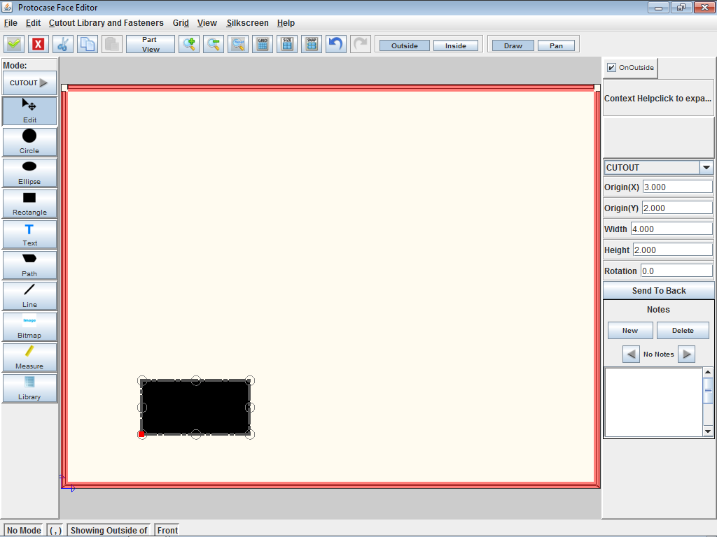
#In the '''Face Editor''' window, create a rectangle cutout approximately as shown below in the bottom left corner.<br><br>[[File:window-faceeditor-ushape-front-rectangle.png|500px|Rectangle cutout on u-shape front face]]<br> | #In the '''Face Editor''' window, create a rectangle cutout approximately as shown below in the bottom left corner.<br><br>[[File:window-faceeditor-ushape-front-rectangle.png|500px|Rectangle cutout on u-shape front face]]<br> | ||
#On the '''Properties''' panel, set the '''Origin(X)''' to "3" and '''Origin(Y)''' to "2". | #On the '''Properties''' panel, set the '''Origin(X)''' to "3" and '''Origin(Y)''' to "2". | ||
| Line 14: | Line 13: | ||
#Click '''Accept & Close'''. [[File:button-acceptclose.png|40px|bottom]] | #Click '''Accept & Close'''. [[File:button-acceptclose.png|40px|bottom]] | ||
#Rotate the model to view both rectangle cutouts. Notice how they are aligned with each other.<br><br>[[File:window-main-ushape-alignedrectangles.png|500px|Rectangle cutouts aligned on front and rear faces]]<br> | #Rotate the model to view both rectangle cutouts. Notice how they are aligned with each other.<br><br>[[File:window-main-ushape-alignedrectangles.png|500px|Rectangle cutouts aligned on front and rear faces]]<br> | ||
| − | |||
You can apply this technique to align cutouts on any two faces of your enclosure. | You can apply this technique to align cutouts on any two faces of your enclosure. | ||
'''See Also:''' | '''See Also:''' | ||
| − | |||
*[[Face Editor#Measure distances|Measuring distances]] | *[[Face Editor#Measure distances|Measuring distances]] | ||
*[[Dimensions:_Displaying_measurements|Displaying measurements for review]] | *[[Dimensions:_Displaying_measurements|Displaying measurements for review]] | ||
| − | |||
Revision as of 13:20, 15 September 2015
This tutorial will show you how to create 4 in x 2 in rectangular cutouts on the front and rear faces so that they are aligned with each other. Note that this procedure uses the absolute origin as the reference point. Please see About the Coordinate System for an explanation of the coordinate system used in Protocase Designer.
- In the Face Editor window, create a rectangle cutout approximately as shown below in the bottom left corner.
- On the Properties panel, set the Origin(X) to "3" and Origin(Y) to "2".
- The rectangle is positioned with respect to the origin in the bottom left corner.
- Set the Width to "4" and Height to "2.
- Click Accept & Close.

- In the 3D View window, rotate the model to show the rear face.
- Click Edit Face
 , then click the rear face. The Face Editor window opens.
 - In the Face Editor window, create a rectangle cutout approximately as shown below in the bottom right corner.
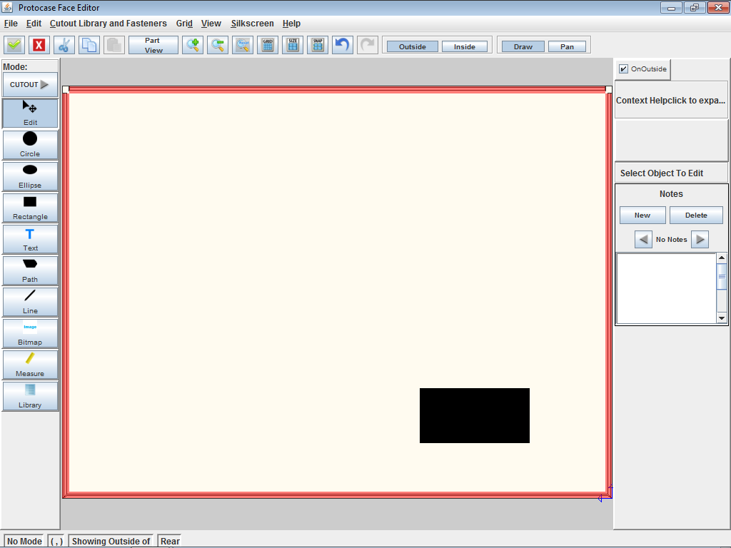
- On the Properties panel, set the Origin(X) to "3" and Origin(Y) to "2" (same as for the front face).
- The rectangle is positioned with respect to the origin in the bottom right corner.
- Set the Width to "4" and Height to "2" (same as for the front face).
- Click Accept & Close.
- Rotate the model to view both rectangle cutouts. Notice how they are aligned with each other.
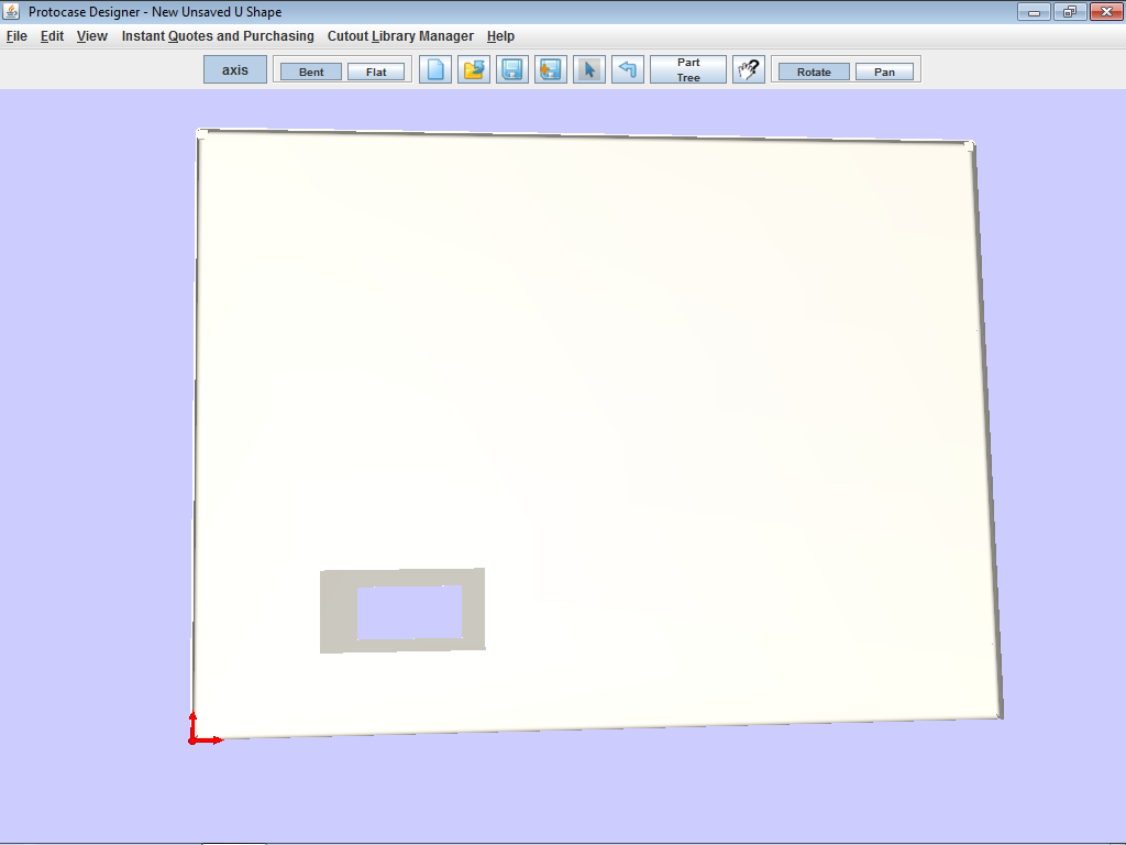


You can apply this technique to align cutouts on any two faces of your enclosure.
See Also: