Difference between revisions of "3D View Window"
m (→Editing a face from the Part Tree) |
m |
||
| Line 1: | Line 1: | ||
=3D View Window overview= | =3D View Window overview= | ||
| − | The 3D View window displays a 3D model of your enclosure that you can manipulate. | + | The 3D View window displays a 3D model of your enclosure that you can manipulate.<br> |
| − | [[File:window-main-labels.png| | + | [[File:window-main-labels.png|500px]]<br> |
'''A: 3D View Toolbar'''<br> | '''A: 3D View Toolbar'''<br> | ||
'''B: Viewport'''<br> | '''B: Viewport'''<br> | ||
=Creating, opening, and saving assembly files= | =Creating, opening, and saving assembly files= | ||
| − | Enclosures are saved as Protocase Designer Assembly | + | Enclosures are saved as Protocase Designer Assembly (.PDA) files. |
| − | + | ||
==Create new assembly file== | ==Create new assembly file== | ||
| − | # | + | #Choose '''File''' > '''New''', or click '''Make New Enclosure From Template''' [[File:Make_new_enclosure_from_template_button_3DView|25px]] in the 3D View toolbar. |
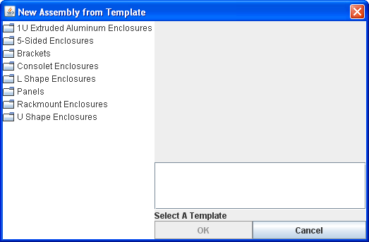
| − | #Select an enclosure category on the left and then select an enclosure type. The New Assembly dialog opens. | + | #Select an enclosure category on the left and then select an enclosure type. |
| − | # | + | #;The New Assembly dialog opens. |
| + | #;[[File:window-newassembly-noselection.png|400px]] | ||
#Modify the enclosure parameters including size, thickness, material, and colour to meet your design requirements. | #Modify the enclosure parameters including size, thickness, material, and colour to meet your design requirements. | ||
| − | # | + | #;[[File:window-newassembly-ushape.png|400px]]<br> |
#Click '''OK''' to view the 3D model. | #Click '''OK''' to view the 3D model. | ||
| − | # | + | #;[[File:window-main-ushape.png|600px]]<br> |
'''Note:''' To create a custom bracket with cutouts and other elements, you use the 3D View window to create them, then you use the Face Editor to customize them and to add them to a face. See '''[[Face Editor#Creating and adding brackets|Creating and adding brackets]]''' for step-by-step instructions. | '''Note:''' To create a custom bracket with cutouts and other elements, you use the 3D View window to create them, then you use the Face Editor to customize them and to add them to a face. See '''[[Face Editor#Creating and adding brackets|Creating and adding brackets]]''' for step-by-step instructions. | ||
| Line 48: | Line 49: | ||
#On the '''Edit''' menu, click '''Edit Enclosure Properties'''. | #On the '''Edit''' menu, click '''Edit Enclosure Properties'''. | ||
#:The Edit Assembly dialog is displayed. | #:The Edit Assembly dialog is displayed. | ||
| − | #:[[File:3D_view_Edit_Properties_dialog.png| | + | #:[[File:3D_view_Edit_Properties_dialog.png|500px]] |
#Change any of the enclosure properties, then click '''OK'''. | #Change any of the enclosure properties, then click '''OK'''. | ||
{{Note|The size of your enclosure must meet all the manufacturing constraints listed at the bottom of the dialog box.}} | {{Note|The size of your enclosure must meet all the manufacturing constraints listed at the bottom of the dialog box.}} | ||
| Line 90: | Line 91: | ||
#On the '''Edit''' menu, click '''Preferences''' to display the preferences dialog box. | #On the '''Edit''' menu, click '''Preferences''' to display the preferences dialog box. | ||
#Select the '''Use Transparency''' check box. | #Select the '''Use Transparency''' check box. | ||
| − | + | '''Note''': Turning on the transparency option does not affect the final product. | |
==Change background color== | ==Change background color== | ||
| Line 113: | Line 114: | ||
=Viewing the Part Tree= | =Viewing the Part Tree= | ||
The Part Tree shows a hierarchical list of all the faces and objects in your enclosure. You can change the name and description of objects as well as open a face in the Face Editor Window directly from the Part Tree.<br> | The Part Tree shows a hierarchical list of all the faces and objects in your enclosure. You can change the name and description of objects as well as open a face in the Face Editor Window directly from the Part Tree.<br> | ||
| − | [[File:window-parttree-ushape-note.png| | + | [[File:window-parttree-ushape-note.png|500px]] |
==Navigate the Part Tree== | ==Navigate the Part Tree== | ||
| Line 136: | Line 137: | ||
#Click a face name on the left. | #Click a face name on the left. | ||
#Click '''Edit Face'''. The '''Face Editor''' window opens. | #Click '''Edit Face'''. The '''Face Editor''' window opens. | ||
| − | #:[[File:window-parttree-ushape-editface.png| | + | #:[[File:window-parttree-ushape-editface.png|500px]] |
| − | + | '''Note''': The Part Tree window can also be accessed from the Face Editor. | |
=Window Preferences= | =Window Preferences= | ||
| − | You can change the background color and the axis color in the 3D View | + | You can change the background color and the axis color in the 3D View. See [[Face_Editor#Face_Editor_Preferences|Face Editor Preferences]] for changing the background color and axis color. (The Preferences dialog box is used for both the 3D View and Face Editor windows,) |
Revision as of 17:09, 22 October 2015
Contents
3D View Window overview
The 3D View window displays a 3D model of your enclosure that you can manipulate.

A: 3D View Toolbar
B: Viewport
Creating, opening, and saving assembly files
Enclosures are saved as Protocase Designer Assembly (.PDA) files.
Create new assembly file
- Choose File > New, or click Make New Enclosure From Template 25px in the 3D View toolbar.
- Select an enclosure category on the left and then select an enclosure type.
- The New Assembly dialog opens.
- Modify the enclosure parameters including size, thickness, material, and colour to meet your design requirements.
- Click OK to view the 3D model.


Note: To create a custom bracket with cutouts and other elements, you use the 3D View window to create them, then you use the Face Editor to customize them and to add them to a face. See Creating and adding brackets for step-by-step instructions.
Open an existing assembly file
- In the 3D View window, choose Open from the File menu, or click the Open button on the toolbar.
- Select the file you want to open.
Save the current assembly file
- Choose Save from the File menu, or click the Save button on the toolbar.
- If this is the first time the assembly is being saved, the Save dialog box will open. Select a location to save the assembly file and type a name for the assembly, then click Save.
Save a copy of the current assembly file
- Choose Save As from the File menu, or click the Save As button on the toolbar.
- In the Save dialog box that opens, select a location to save the file and type a new name for the assembly, then click Save.
Selecting rackmounts
When you select a rackmount, the parameters include the Full Height Chassis check box. Selecting this checkbox causes the screws to be countersunk, and the enclosure the same height as the front of the rackmount.
Selecting a screw type
Templates include screw types and colors.
To select a screw
- Click New.
- The New Assembly from Template dialog opens.
- Select the item you want to use.
- The item's specifications are displayed. If it includes screws, the Screw Type is displayed with a default value. (The field is not displayed for brackets or panels, since those item do not use screws. It is also not displayed if Protocase has not yet implemented the screws for the template; in this case you can contact Protocase to request a screw type.)
- Click the down-arrow for the Screw Type and select the color (Black, Natural [Zinc], or Stainless) and type (Flathead or Panhead) you want.
- Click OK.
Changing enclosure properties
At any point after you create a new enclosure you can modify your enclosure properties such as size, thickness, material, and colour.
- On the Edit menu, click Edit Enclosure Properties.
- The Edit Assembly dialog is displayed.
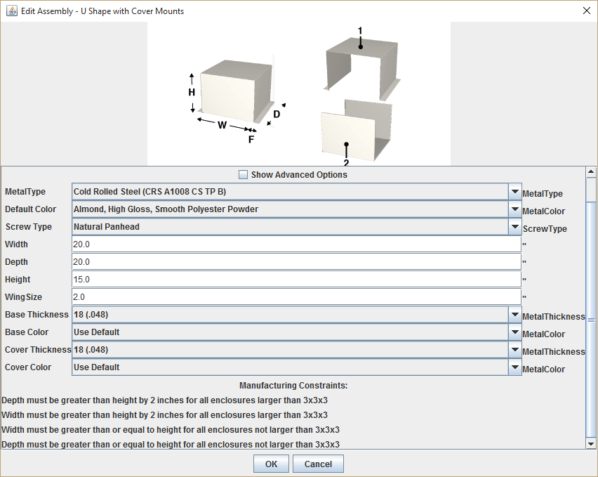
- Change any of the enclosure properties, then click OK.

- Note: The size of your enclosure must meet all the manufacturing constraints listed at the bottom of the dialog box.
Viewing the model
There are several controls to allow viewing and manipulating the 3D model of your enclosure.
Rotate model
The Rotate command spins the model around its center.
- On the 3D View toolbar, click the Rotate button.
- Drag the model to rotate it to the desired orientation.
Pan model
To move the model around the plane of the viewport, do any of the following:
- Right-click the model and drag it.
- Press and hold down the <Alt> key, then click and drag the model.
- Click the Pan button on the toolbar, then click and drag the model.
Zooming
To zoom the model in or out, rotate the wheel button forward or backward.
Notes
- The model zooms in/out from the centre of the viewport, regardless of the pointer location.
- If your pointing device does not have a wheel, open the Face Editor and use the Zoom In and Zoom Out buttons on the toolbar or the Zoom commands in the View menu.
Show/Hide Parts
The Show/Hide Parts command lets you view inside the model by hiding one or more parts.
- On the View menu, click Show/Hide Parts. The Show/Hide Parts dialog box is displayed.
- Select or clear the appropriate check boxes to show or hide parts.
Toggle flat/bent view
The Toggle Flat and Bent commands displays the enclosure parts as they are laid out prior to the bending process during manufacturing. These commands are for reference only, and do not affect the manufacturing of the final enclosure. You can do either of the following:
- On the Toolbar, click the Flat button to display the model in a flat view, or click the Bent button to display the model in the default bent view.
- Choose Toggle Flat from the View menu to change between the two views.
Reset view
The Reset View command displays the model in the center of the viewport in its original orientation.
- Click the Reset View button on the toolbar, or choose Reset View from the View menu.
Use Transparency
The transparency option makes exclusion zones and the background of silkscreen images transparent. This allows you to view features that might be hidden behind exclusion zones or silkscreen images.
- On the Edit menu, click Preferences to display the preferences dialog box.
- Select the Use Transparency check box.
Note: Turning on the transparency option does not affect the final product.
Change background color
The Change background color command allows for customizing the background color of the viewport.
- On the Edit menu, click Preferences to display the preferences dialog box.
- Click Change Background Color. A dialog box opens, where you can customize the background color of the viewport.
- Select the Swatches, HSB, RGB.
Change axis color
The Change Axis Color command allows for customizing the color of the coordinate system axis displayed on the model.
- On the Edit menu, click Preferences to display the preferences dialog box.
- Click Change Axis Color. A dialog box opens, where you can customize the axis colour.
Editing a face using the Face Editor
To customize your enclosure, you add features such as cutouts, silkscreen, exclusion zones, and construction lines to a face in the Face Editor Window.
To open the Face Editor:
- Rotate the model to show the face you want to edit.
- Click the Edit Face button on the toolbar.
 . The pointer will change to a crosshair.
 - Click a face to edit. The Face Editor window opens.
Viewing the Part Tree
The Part Tree shows a hierarchical list of all the faces and objects in your enclosure. You can change the name and description of objects as well as open a face in the Face Editor Window directly from the Part Tree.

- Click the icon to the left of a face to display the objects on that face below.
- Click an object name to display description, and notes on the right of the Part Tree window.
Change object name and description
- Click an object name on the left.
- Type a new name or description on the right.
Add/Delete notes
You can add notes to parts, faces, and objects for your own reference or to provide additional information to technical support such as "Please scrub this with a scouring pad". You can also use it to place features that might not be permitted in Protocase Designer® but can be manufactured with certain restrictions. For example, you could create a circle using construction lines near the edge of a face on the exclusion zone (where you wouldn't normally be able to place a self-clinching standoff) and add a note "Add 6-32 x 3/8" standoff here".
- Click an object name on the left.
- Do one of the following:
- If there are no notes, type a note in the notes field.
- If there are existing notes, click New Note and type a note in the notes field.
- Click the arrows to view each note.
- Click Delete Note to delete the currently displayed note.
Editing a face from the Part Tree
- Click a face name on the left.
- Click Edit Face. The Face Editor window opens.

Note: The Part Tree window can also be accessed from the Face Editor.
Window Preferences
You can change the background color and the axis color in the 3D View. See Face Editor Preferences for changing the background color and axis color. (The Preferences dialog box is used for both the 3D View and Face Editor windows,)