CNC Machined Parts
Now you can design fully finished machined parts and have them in hand in as little as 2-3 days, directly within Protocase Designer!
https://www.protocase.com/products/cnc-machining/
Contents
Getting Your Design Started
Protocase Designer now includes a Machined Shapes category under templates.
To begin, select the Machined Cube template, you can expect more shapes & templates to come in the future!
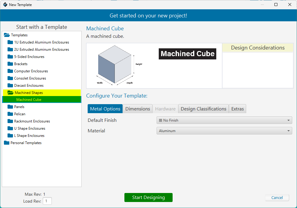
You can customize the finish, material, and dimensions of your part, as well as add Chemical Film Conversion Coating for Aluminum, and Passivation for Stainless Steel. Click on the Extras tab and check the box labelled Chemical Conversion Coating or Passivation.
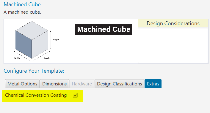
Once you've selected your desired material, finish and dimensions - click the "Start Designing" button to view your part in 3D and begin making some edits!
Creating Your First Sketch
A Sketch is the starting point of most designs. Think of it like drawing a 2D shape on paper. In CAD software, a sketch is created on a flat surface (like the face of a part or a base plane) and consists of lines, circles, arcs, and other geometric shapes. These 2D outlines are the foundation for creating 3D features like holes, pockets, or solid bodies.
Example: You might sketch a circle to define the base of a cylinder, or a rectangle to later cut a pocket into a part.
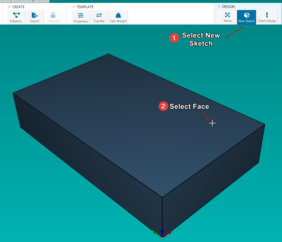
In the 3D view, you need to first select the face which you want to create a sketch on. You can do so by clicking on New Sketch and selecting the face.
Note: You can have multiple sketches on the same face.
Drawing 2D Shapes
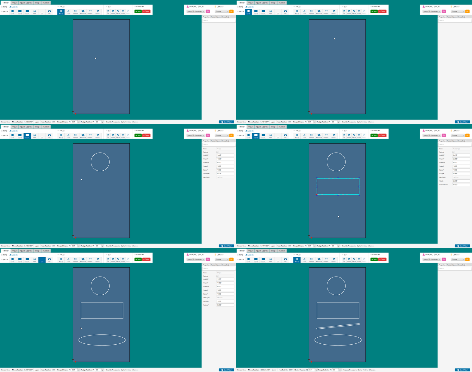
After selecting your face to draw your sketch on, it will open up the 2D sketch editor. For a more detailed look at this window, see Face Editor Overview
The following are the different shapes you can draw in your sketch:
- Circle
- Ellipse
- Rectangle
- Line
- Arc
- Custom Path
To begin drawing shapes, select your desired shape from the DRAW menu above, hold left click and drag your mouse to start drawing the path. Release your mouse button to finish the shape.
Once you're happy with your sketch, click Save
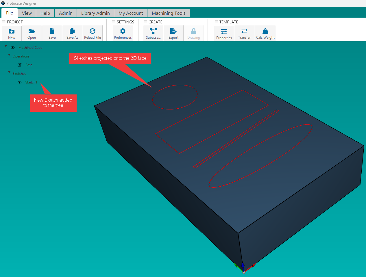
Back in the 3D view, your newly created sketch will be visible indicated by the red outlines on the face.
Edit Existing Sketches
Once you have a sketch drawn, if you want to modify something afterwards there are two ways to go about it.
Note: Editing any sketch that has an operation already applied to it, will update the operation automatically!
1. Machining Tree:
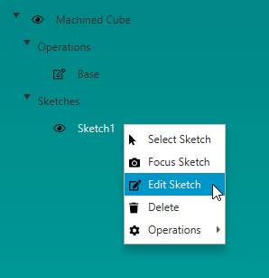
- On the left side of the editor is the machining tree, which shows a list of your operations & sketches. Find the sketch you want to modify and right click it, then choose Edit Sketch
2. Sketch Selection Dialog
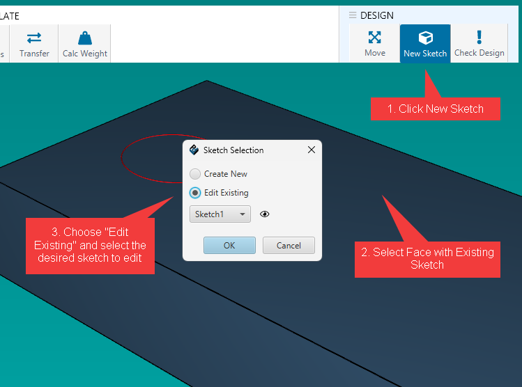
- When selecting "New Sketch" on a face that already has a sketch present, you'll be prompted with a dialog and the options to continue creating a new sketch on this face, or to choose one of the existing sketches to edit. If you proceed with "Edit Existing" then it will just display that sketch in the 2D editor as mentioned above.
Applying Operations
An Operation is a step in the CAD model that modifies the geometry of the part. Each operation is based on a 2D sketch. Think of operations as building blocks stacked one after the other to shape your final part.
Usage: Common operations include extrusion, cut, fillet, and hole. For example, “Extrude this sketch” or “Pocket this area.” Each operation modifies the part and appears in the feature history or timeline.
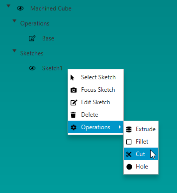
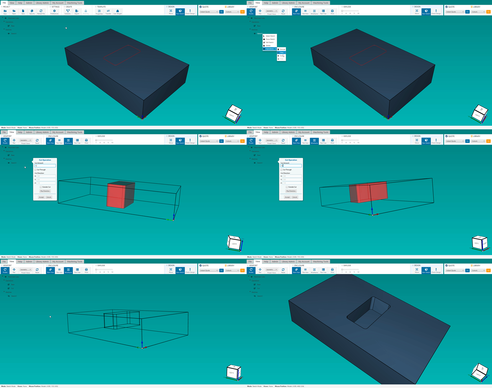
To apply an operation to a sketch, right click on the sketch from within the machining tree, and hover the Operations menu, and click your desired operation. Note: if an operation is disabled, it means your sketch is not compatible with the operation. For instance, the Hole operation is disabled if your sketch does not contain any circle paths.
While applying an operation, you will see a transparent red "preview" shape that the operation generates within the model. It's often useful to view your model in Wireframe mode during this, as it gives you a better representation of how the operations shape will change your geometry. This can be done by going to the View tab in the editor, and clicking Wireframe.
In Protocase Designer we have the following operations:
Cut Operation
- The Cut Operation is used to create pockets, they can be either blind-pockets (fixed depth, doesn't cut all the way through) or through-pockets (cuts straight through to the other side)
- You can enter the Cut Amount, which controls how deep the pocket will go, or choose Cut-Through which will automatically cut straight through to the other side of the part.
Extrude Operation
- Extrude Operation takes a 2D sketch and pushes or pulls it into 3D space to add or remove material. You can extrude a shape outward to create solid material, or inward to remove material.
- You can choose the extrusion amount as well as flipping the direction inward and choosing to make a cut.
Hole Operation
- The Hole Operation is used to create different hole features, such as:
 * Countersinks
 * Counterbores
 * Tapped Holes
 * Drilled Holes
Fillet Operation
- TODO
