Dimension Drawings
As of version x.x.x, you can now create fully dimensioned drawings of your design, and store them directly within your PDA file or export them to PDF format!
Getting Started
To get started with dimension drawings, just open an enclosure and click the Drawing button on the main toolbar, under the File tab.
Dimensioned Views Creator Dialog
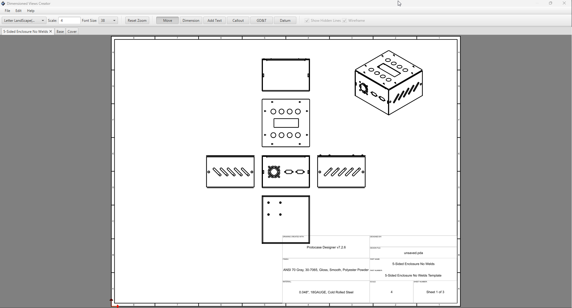
Once you click Create Drawing it will take a moment to generate views for your design, and the following dialog will open:
By default, the initial page Designer will generate will be for the full assembly with all view orientations, including isometric.
In addition to the assembly page, it will create a page for each part in your design, with all view orientations.
Changing Page Size & Scale
The page size and scale can be changed using the options in the toolbar.
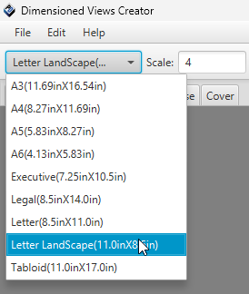
For page sizing, it comes with all of the common page sizes pre-defined, you just need to select the one you want from the drop down menu.
For page scale, just enter your preferred scale into the text box and hit enter. Note, page scale must be a whole number. Decimal values will not work
Changing Font Size
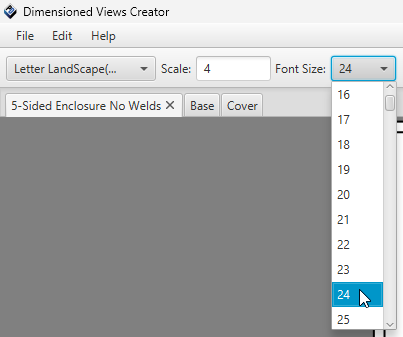
To modify the font size of text in your page, select a size from the drop-down menu located in the toolbar.
Note: When modifying font size for your page, it will effect all text objects within the page, except for the title block data. This includes:
- Text Notes
- Callouts
- Dimension Lines
- Datum Frames
- Any GD&T features.
Toolbar Modes
The toolbar contains toggle buttons for changing the mode of the current page editor. These are used for adding features into your drawing, or moving your views around. They include:
- Move Mode
- Dimension Mode
- Text Mode
- Callout Mode
- GD&T Mode
- Datum Mode
Move Mode
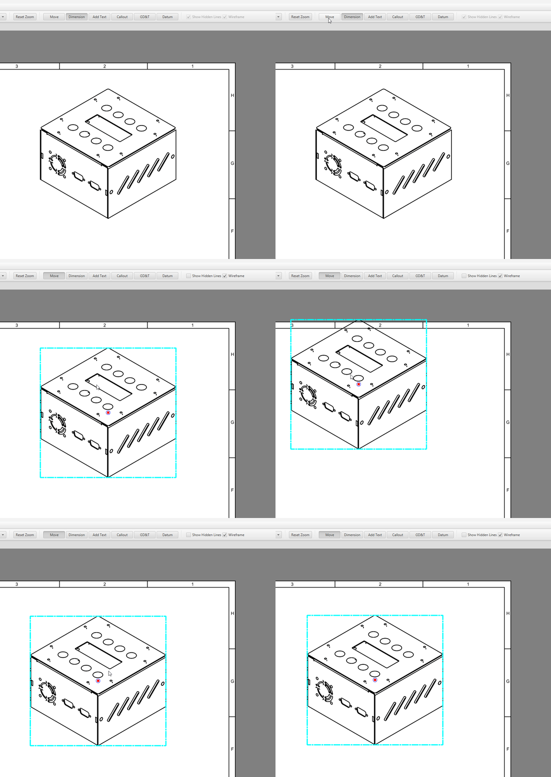
This is the default mode of the editors. To move your views or other features around your page, select the "Move" toggle button, and then left click and drag your object within the page. At any point, pressing the Escape key will reset your mode back to Move.
Dimension Mode
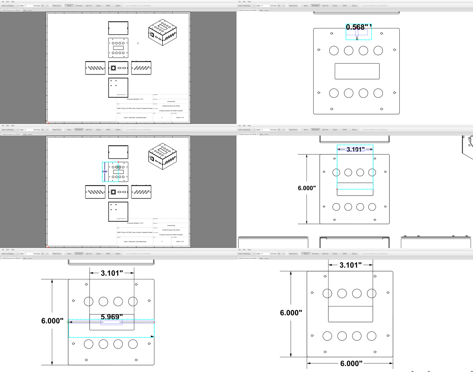
The Dimension mode lets you display the distance between any two points on your views.
- On the toolbar, select the "Dimension" toggle button.
- Click the first endpoint of the distance you wish to measure, then move the cursor.
- As you begin to move the cursor, the distance between the endpoint and the cursor position is displayed.
- When the cursor is near an object, it snaps to the important points of the object (its center, or one of the compass points on its outline), a green circle is drawn around the snap-to point, indicating it is a valid point of selection.
- Click the second endpoint of the distance you wish to measure.
- A second line parallel to the first line is drawn, and the distance between the lines is displayed.
- Next, move your cursor to position the dimension line to your desired location, and click again to place your lines into the face.
- Finally, move your cursor to position the text within the dimension line, and click again to place your text into the face.
- At any point you can move your dimension line after it has been placed by selecting it and dragging your mouse while in Move mode.

