Difference between revisions of "Dimension Drawings"
(→Core Features) |
(→Creating) |
||
| Line 209: | Line 209: | ||
#Once finished, press Enter to place the text onto the page. | #Once finished, press Enter to place the text onto the page. | ||
| − | [[File:Creating Datums Dialog.gif | | + | [[File:Creating Datums Dialog.gif | 800px]] |
===Moving and Editing === | ===Moving and Editing === | ||
Revision as of 16:17, 6 October 2025
As of version 7.2.7, you can now create fully dimensioned drawings of your design, and store them directly within your PDA file or export them to PDF format!
If you encounter any issues, or would like to provide any feed please send us an email at designersupport@protocase.com
Contents
Getting Started
To get started with dimension drawings, just open an enclosure and click the Drawing button on the main toolbar, under the File tab.
Dimensioned Views Creator Dialog
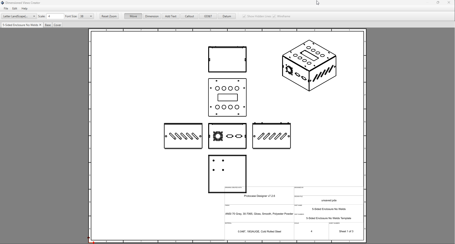
Once you click Create Drawing it will take a moment to generate views for your design, and the following dialog will open:
By default, the initial page Designer will generate will be for the full assembly with all view orientations, including isometric.
In addition to the assembly page, it will create a page for each part in your design, with all view orientations.
Changing Page Size & Scale
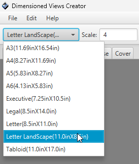
The page size and scale can be changed using the options in the toolbar.
For page sizing, it comes with all of the common page sizes pre-defined, you just need to select the one you want from the drop down menu.
For page scale, just enter your preferred scale into the text box and hit enter. Note, page scale must be a whole number. Decimal values will not work
Changing Font Size
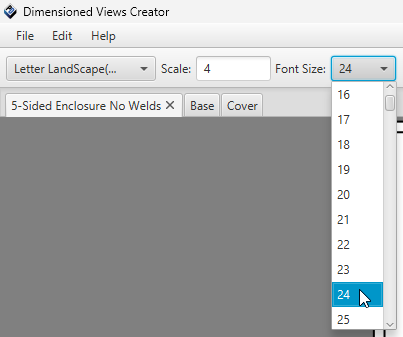
To modify the font size of text in your page, select a size from the drop-down menu located in the toolbar.
Note: When modifying font size for your page, it will effect all text objects within the page, except for the title block data. This includes:
- Text Notes
- Callouts
- Dimension Lines
- Datum Frames
- Any GD&T features.
Toolbar Modes
The toolbar contains toggle buttons for changing the mode of the current page editor. These are used for adding features into your drawing, or moving your views around. They include:
- Move Mode
- Dimension Mode
- Text Mode
- Callout Mode
- GD&T Mode
- Datum Mode
Move Mode
This is the default mode of the editors. To move your views or other features around your page, select the "Move" toggle button, and then left click and drag your object within the page. At any point, pressing the Escape key will reset your mode back to Move.
Tip: to move multiple items at once, select all objects you want to move (using window-select or shift + left-click) and hold shift, then left click and drag in the page to move all selected objects at once while keeping their positions relative to one another.
Dimension Mode
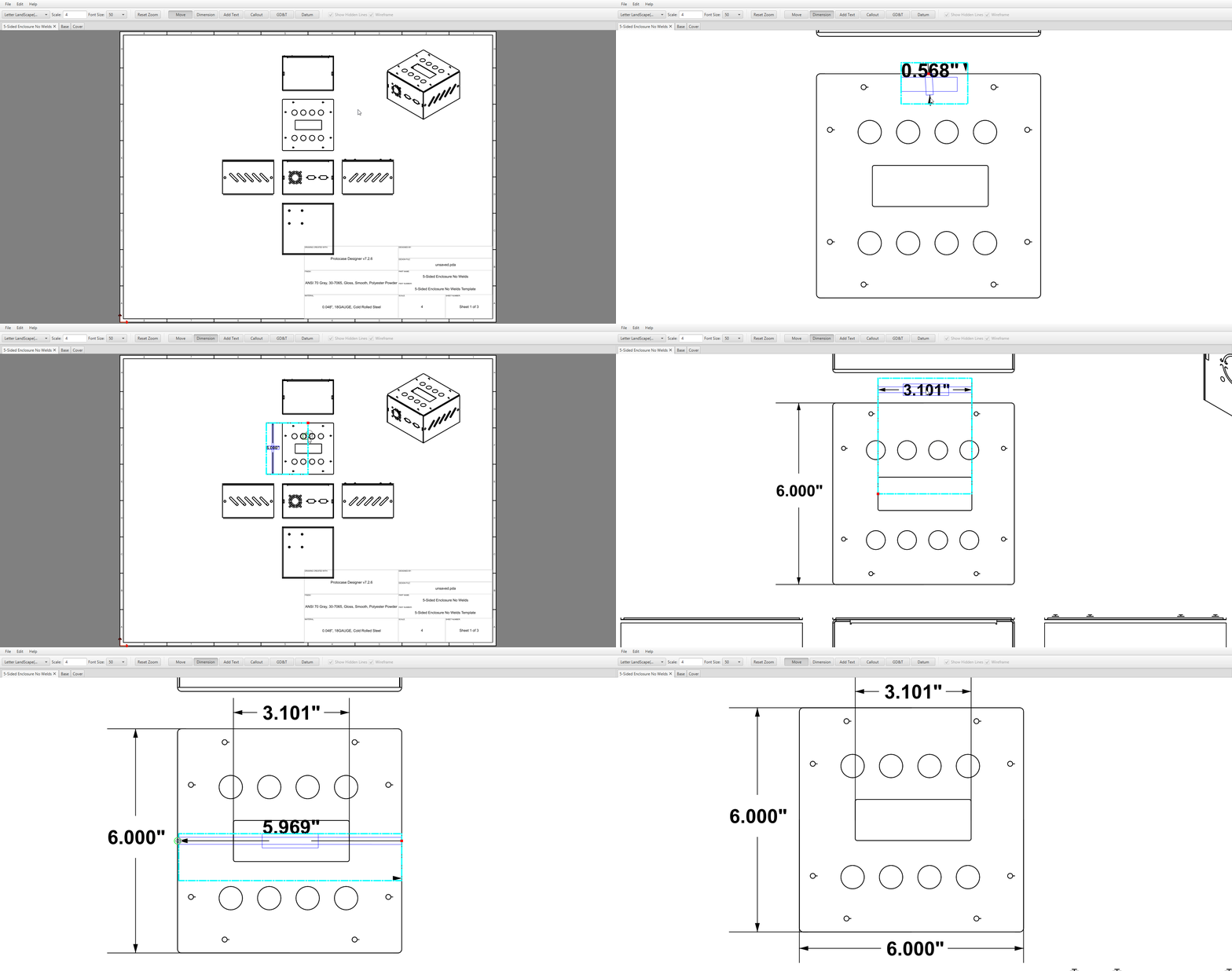
The Dimension mode lets you display the distance between any two points on your views.
- On the toolbar, select the "Dimension" toggle button.
- Click the first endpoint of the distance you wish to measure, then move the cursor.
- As you begin to move the cursor, the distance between the endpoint and the cursor position is displayed.
- When the cursor is near an object, it snaps to the important points of the object (its center, or one of the compass points on its outline), a green circle is drawn around the snap-to point, indicating it is a valid point of selection.
- Click the second endpoint of the distance you wish to measure.
- A second line parallel to the first line is drawn, and the distance between the lines is displayed.
- Next, move your cursor to position the dimension line to your desired location, and click again to place your lines into the face.
- Finally, move your cursor to position the text within the dimension line, and click again to place your text into the face.
- At any point you can move your dimension line after it has been placed by selecting it and dragging your mouse while in Move mode.
Text Mode
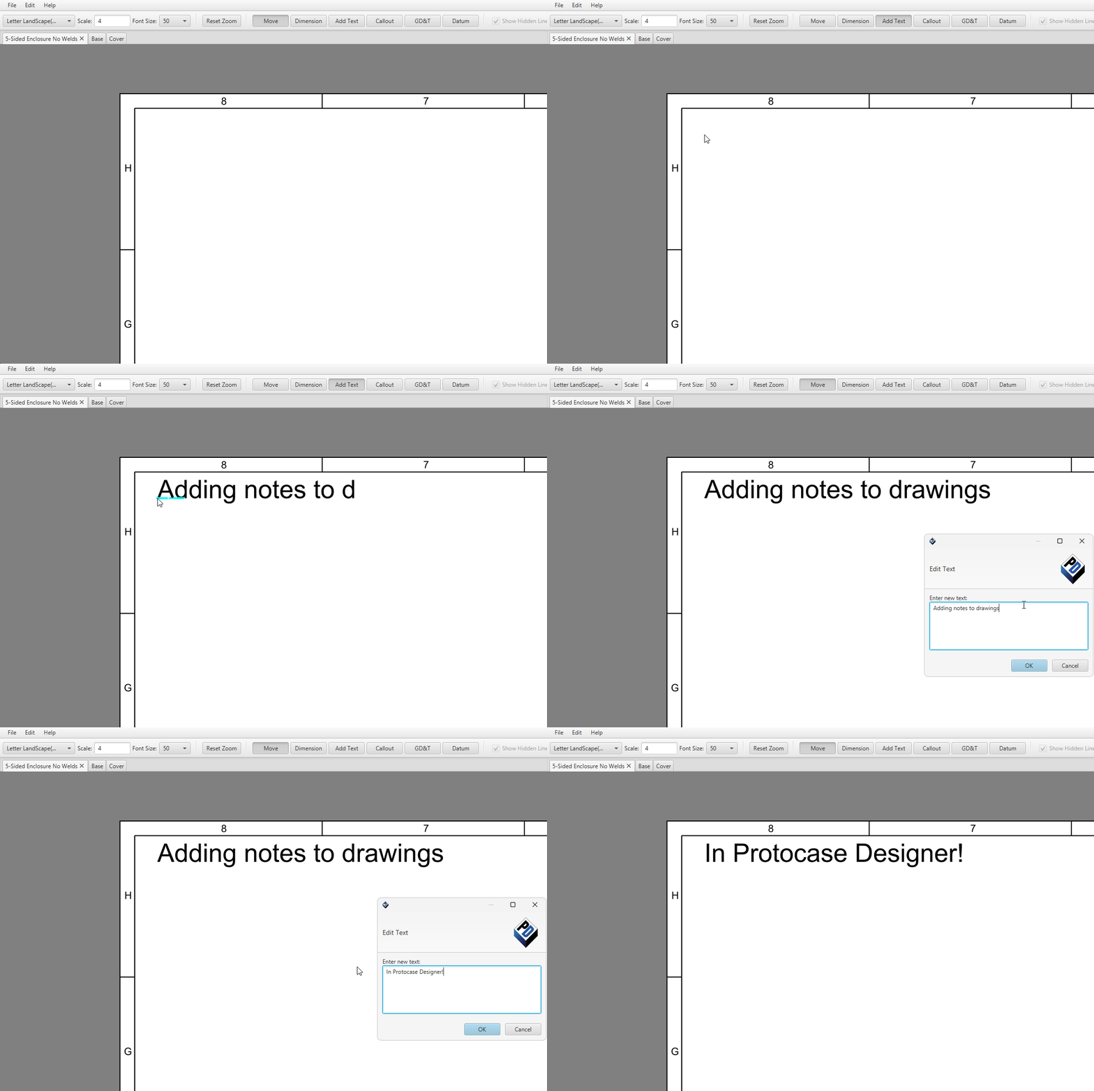
The text mode can be used to add notes to your drawing.
- To enter text mode, select "Add Text" toggle button from the toolbar.
- Left click in the page where you'd like the note to be placed.
- Start typing, and you should start to see your note being drawn in the page.
- Once finished, press Enter to place the note into the page.
- To edit your text after it's been placed, simply double click it while in Move Mode to open the edit dialog.
To add a single note on multiple lines, you can press Shift + Enter while typing to start the new line.
Callout Mode
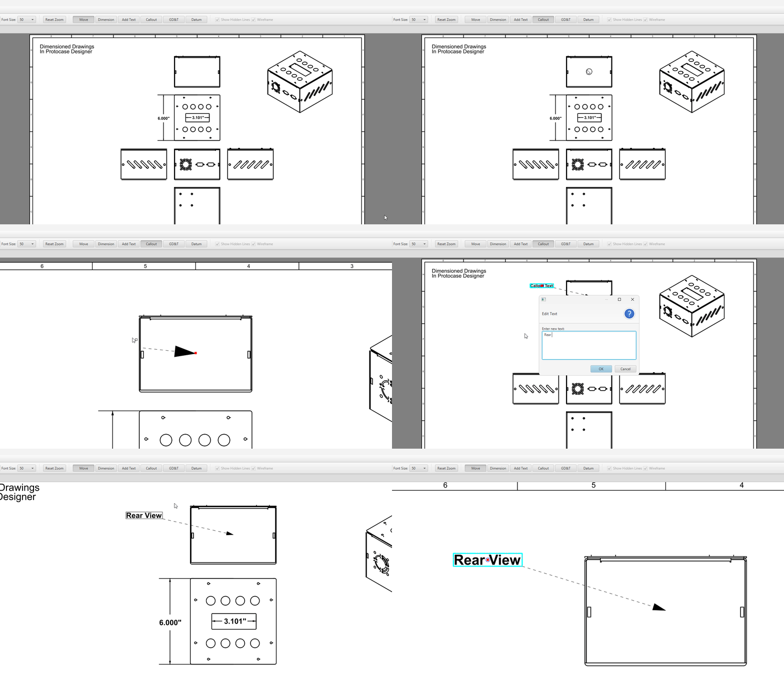
A call out is similar to a text note, with the addition of a leader arrow pointing to a feature in your drawing.
- To enter call out mode, select the "Callout" button from the toolbar.
- Select one of the snap points over the feature you're looking to call out by left clicking.
- An arrow leader will now follow your cursor, pointing to the initial snap point.
- Left-click in the page where you want your call out positioned.
- Enter the text for your call out
- Press OK.
To edit the text of your callout, double click on the text while in move mode to open the edit text dialog.
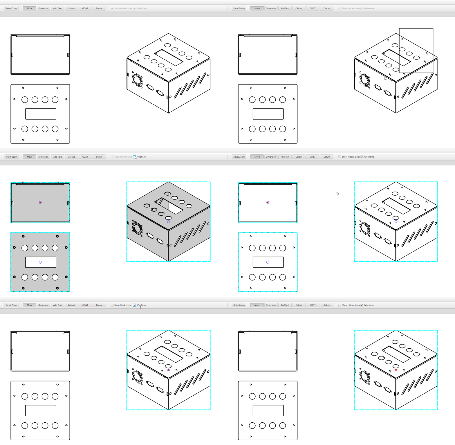
Showing Hidden Lines
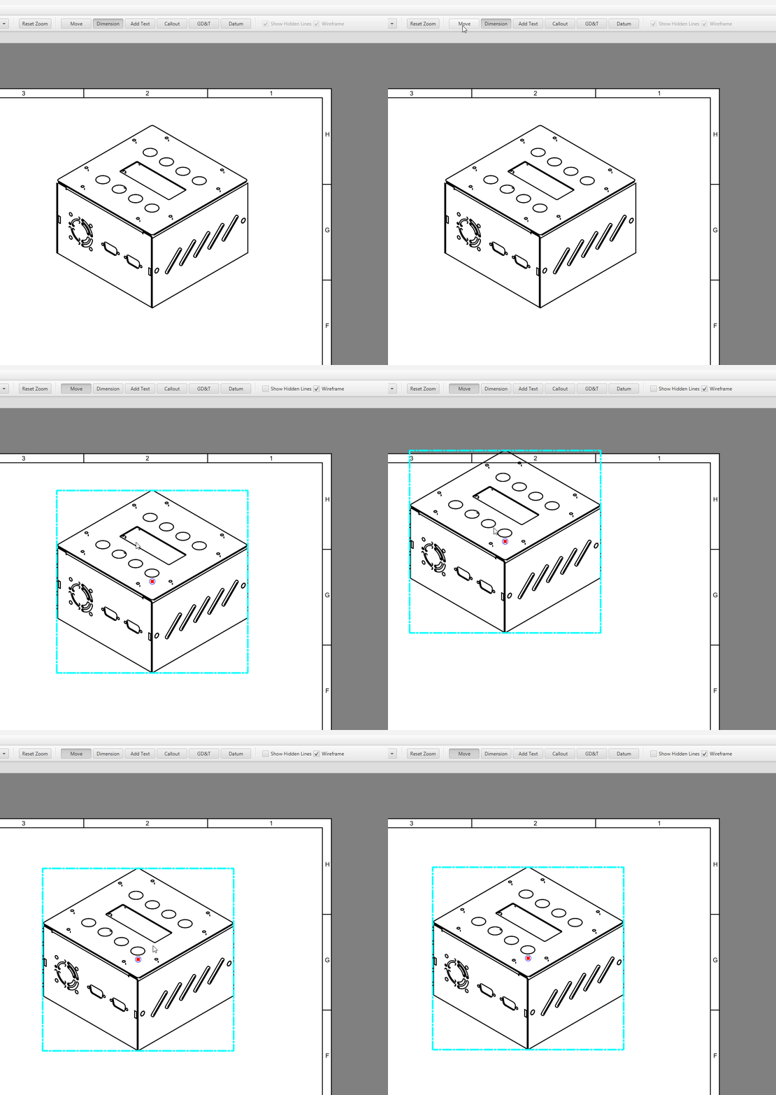
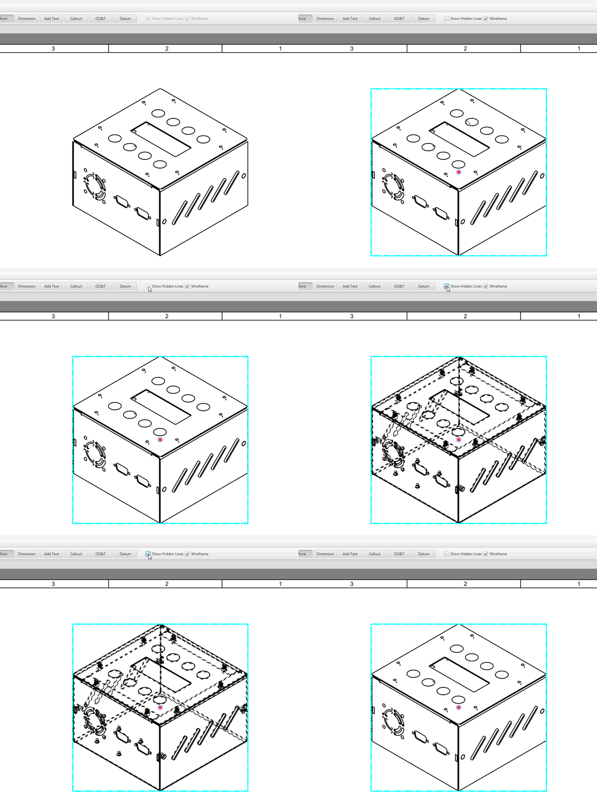
The "Show Hidden Lines" toggle, allows you to toggle the visibility of the hidden lines for the selected views wireframe.
Select a view, or multiple views - and click the Show Hidden Lines checkbox to toggle their visibility.
Wireframe Toggle
The wireframe checkbox allows you to toggle between a wireframe or a filled view for your selected view(s).
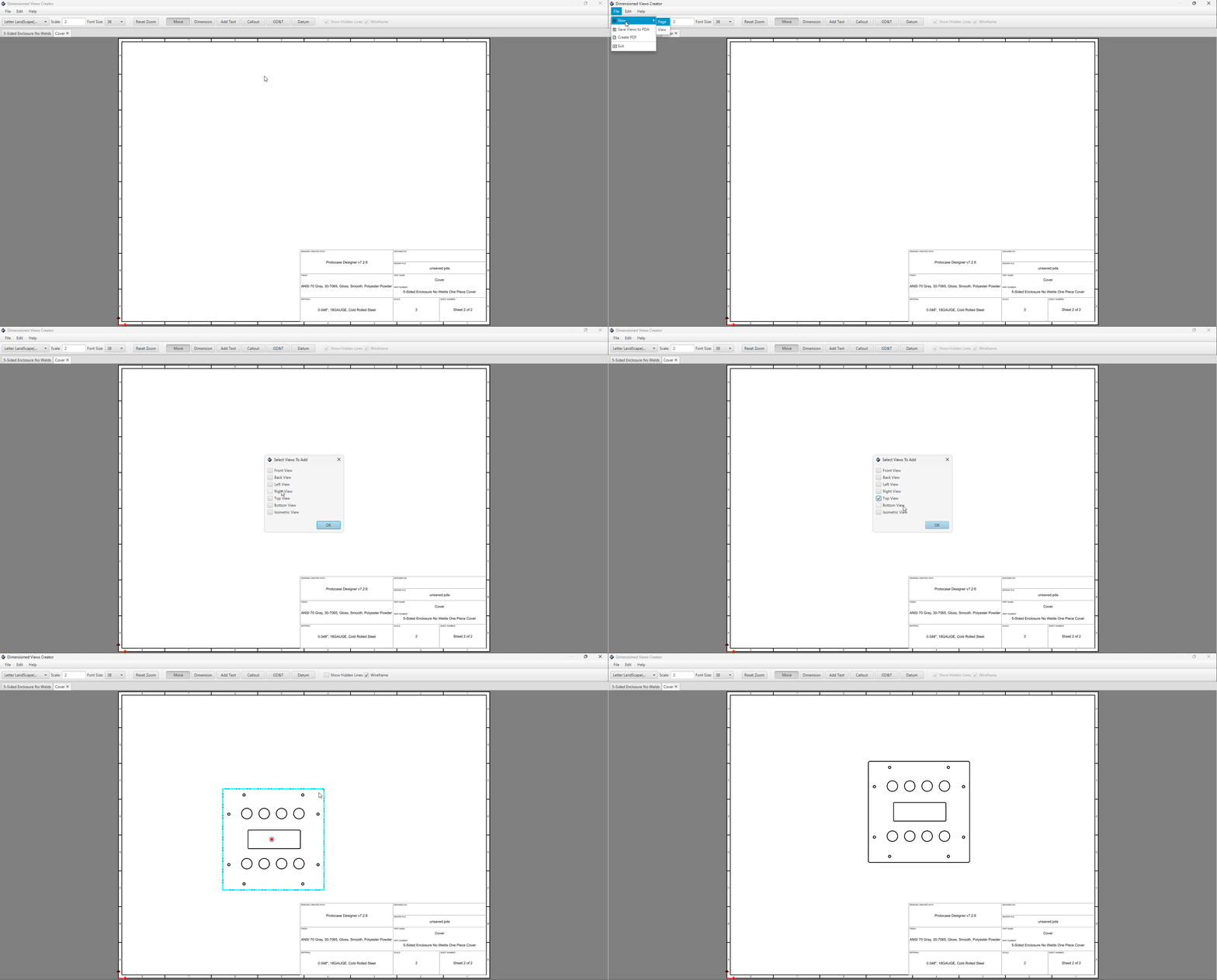
Adding New Views
To add a new view to your page, do the following:
- Click File from the top menu.
- Click New
- Click View from the sub menu.
- Select which view(s) you'd like to add into the page.
- Click OK, and each selected view will be generated and added to your page.
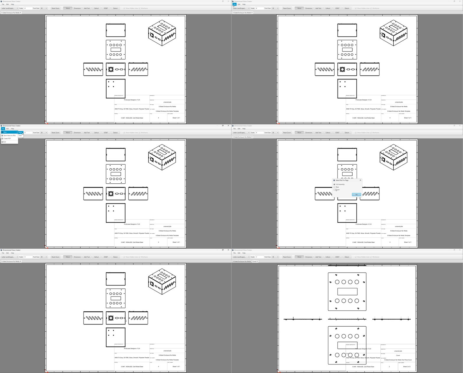
Adding New Pages
To add a new page to your drawing, do the following:
- Click File from the top menu.
- Click New
- Click Page from the sub menu.
- Select which part, or full assembly you want to generate views for to add into the page.
- Click OK, and each view orientation will be generated for the chosen part and added to the page.
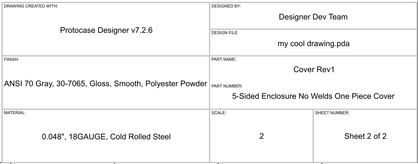
Title Blocks
The title block is the section along the lower right corner of the page which contains key information about your drawing, including:
- Software Version the drawing was created with.
- The authors name
- File name
- Finish of the part
- Part Name & Part Number
- Material of the part
- Page Scale
- Page Number
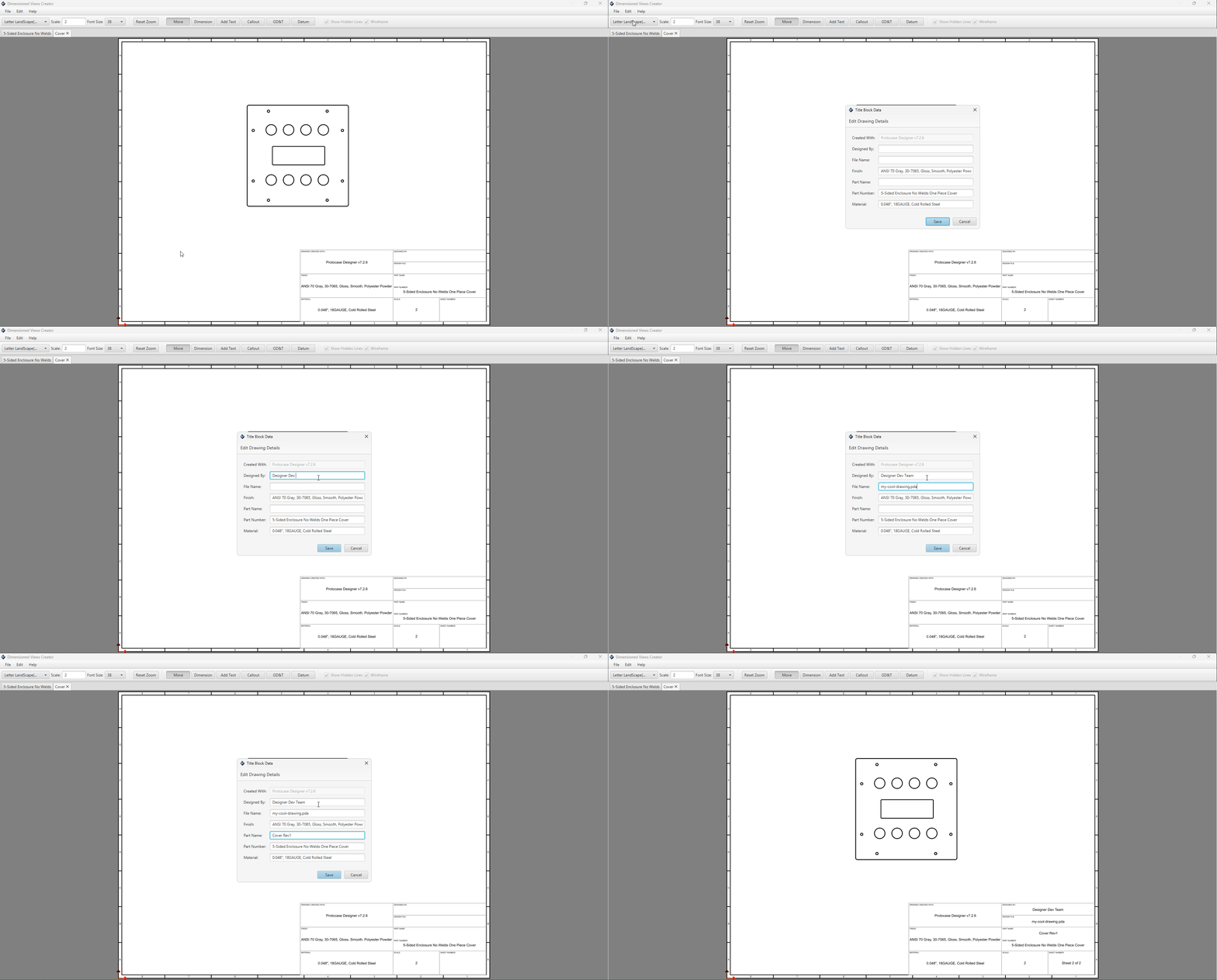
Designer will generate default values for all these sections based on your design when you create your drawing - however they're all easily editable.
To edit the title block data, do the following:
- Click the Edit menu along the top of the dialog
- Select "Edit Title Blocks"
- Update the fields with your desired values.
- Click OK.
Page Zones
The page zones act as a grid system. dividing your pages into labeled areas. Their purpose is to make it easier to locate and reference specific features, notes, or revisions on the drawing.
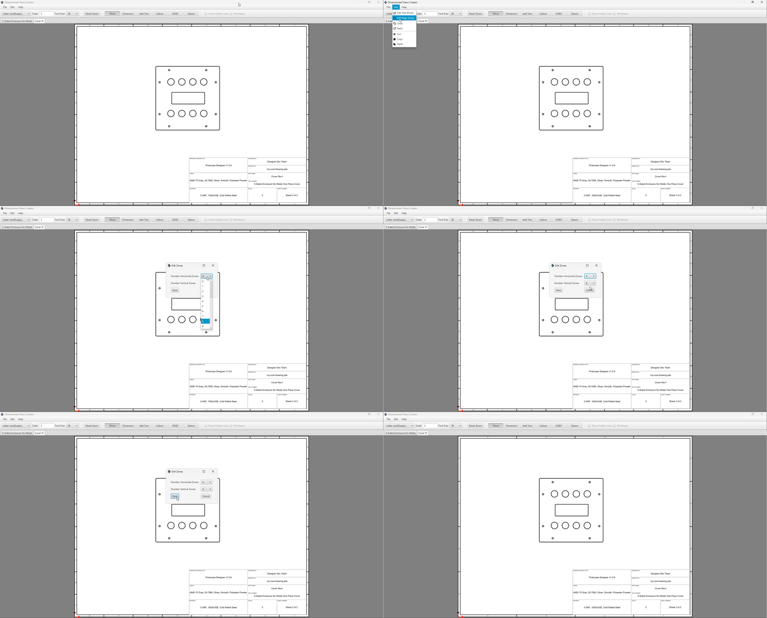
These are auto-generated when you create a page, but you can edit them afterwards.
- Click the Edit file menu
- Click Edit Page Zones
- Choose your desired number of horizontal zones.
- Choose your desired number of vertical zones.
- Click Save to update your page zones.
Saving Your Drawing
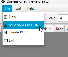
You can save your drawing directly into your PDA file by doing the following:
- Navigate to the File menu
- Click "Save Views to PDA"
Now the next time you open your design, you can re-open your existing drawing by clicking the same "Drawing" button from the toolbar menu in the 3D editor.
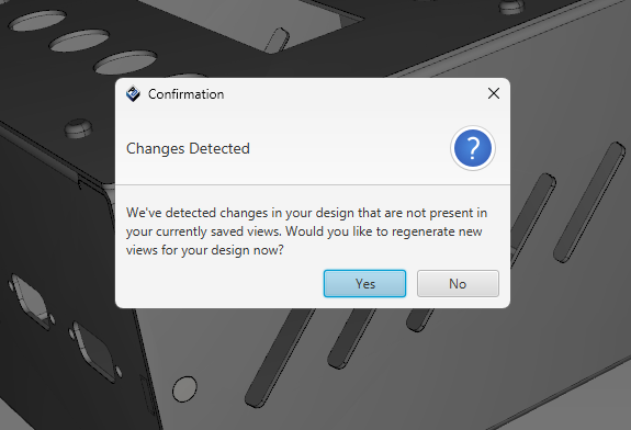
Tip: If you've modified your design since last saving your drawings into your PDA file, the next time you open the dimension drawings editor, you'll see the following dialog asking if you'd like to re-generate the views.
If you don't want to re-generate everything from scratch, you can choose No and simply add a new view for specific parts by using the Add Views or Add Page features.
Creating PDF Drawing
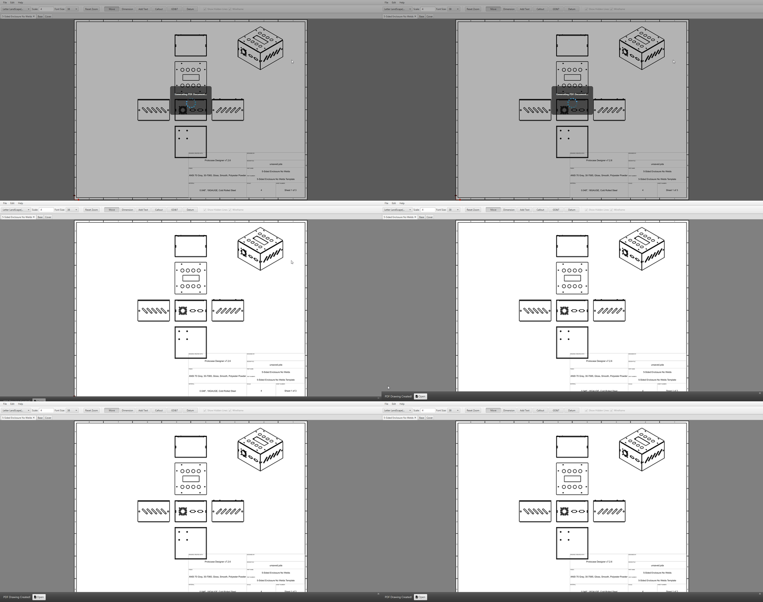
To export your drawing to PDF:
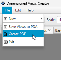
- Navigate to the File menu
- Click Create PDF
- A file browser dialog will open, enter a file name and select a destination to save your file to.
- Once the PDF is created, you'll see a banner along the bottom with an Open button to view your PDF.
Geometric Dimensioning & Tolerancing (GD&T)
In Geometric Dimensioning and Tolerancing (GD&T), a standardized system is used to define and communicate engineering tolerances and part geometry. GD&T uses a symbolic language to precisely describe the size, shape, orientation, and position of features on a part. This allows engineers, machinists, and inspectors to understand how a component should be manufactured and how it will fit or function within an assembly.
Protocase Designer GD&T viewing and editing dialogues are accessible via toggle buttons at the top of drawings page.
Datums
A datum is a theoretical reference point, line, or surface on a part that serves as the origin for measurement and manufacturing. It acts as a frame of reference against which other features are defined and inspected, ensuring consistency in how parts fit and function together. Datums are usually selected from important functional surfaces or features, such as a flat face, a hole, or an axis, and are labeled with capital letters (A, B, C, etc.).
Creating
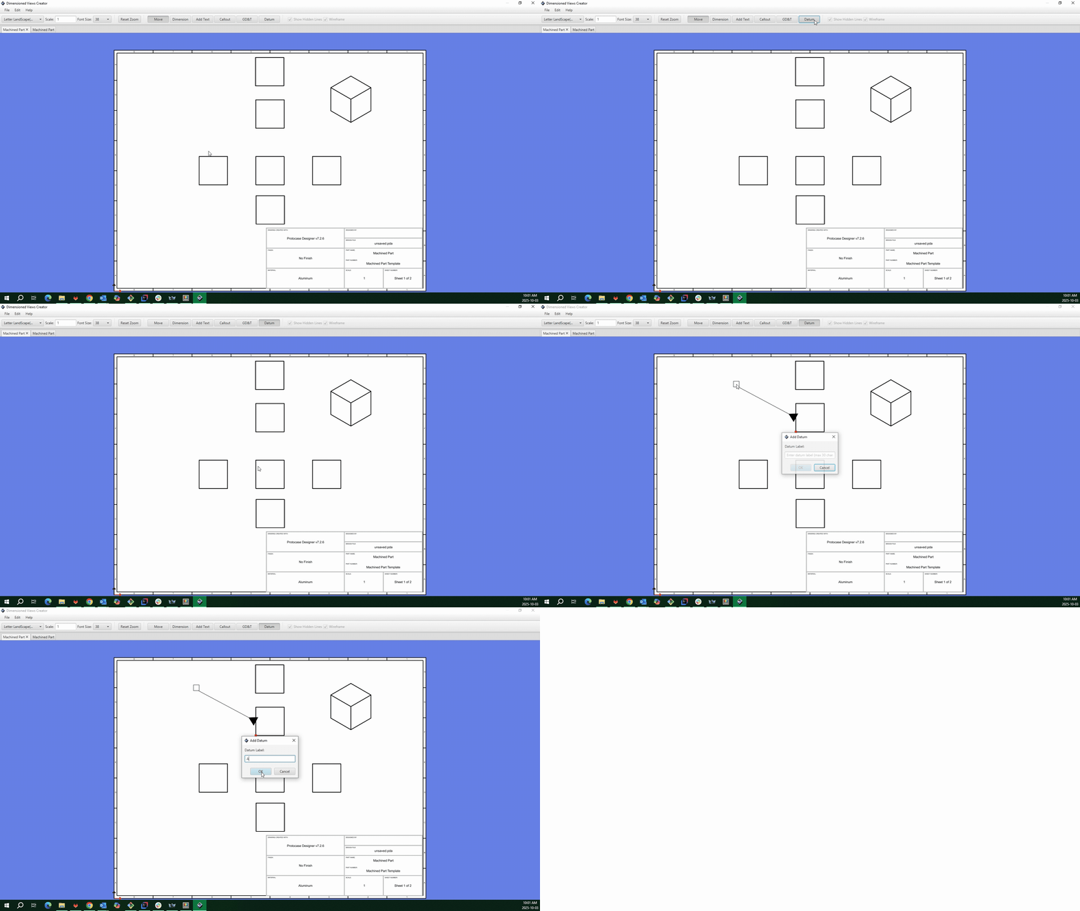
Datum mode can be activated by selecting the datum toggle button from the toolbar.
- To enter Datum mode, select "Datum" toggle button from the toolbar, it will be highlighted after selection.
- Moving the mouse to over over key features in your design a small circle with appear known as a snap point.
- Left click in the snap point and this will pace an arrow to the selected postion of the datum label.
- Left click again to place the datum label and start entering text.
- Start typing, and you should start to see your text being drawn in the dialog box.
- Once finished, press Enter to place the text onto the page.
Moving and Editing
- To edit your text after it's been placed, simply double click it while in Move Mode to open the edit dialog.
- When you edit the text in the datum all datum references with that label will be updated on that design page.
- To move label, simply hover over the text label and the cursor will change to demonstrate the ability to move the label.
- Left click on the label and drag to the new preferred location.
You can move multiple datum labels at the same time by selecting them with the shift button held down. With the shift button down drag the mouse to a new location.
Deleting
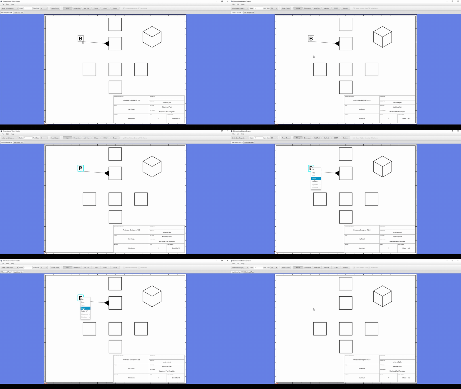
You can delete datums by either selecting the datum label and pressing delete on the keyboard. Alternatively, you can select the datum label and right-click and select delete from the drop-down box.
Other Operations
When you right-click on a single selected datum you have other operation options to copy the datum, paste, or rotate the text 90 degrees. Coping and pasting datums will reference the same feature point with a new label with the same text.
If you right-click a datum after selecting multiple datums operations to positional align or distribute the positions of the labels.
Feature Control Frames
Getting Start
A Feature Control Frame (FCF) is the core communication tool used in Geometric Dimensioning and Tolerancing to define the specific geometric requirements of a feature on a part. It provides a standardized, symbolic way to describe how much variation in form, orientation, location, or profile is acceptable. Feature Control Frame's group together multiple pieces of communication about material, position, and datums.
Creating Feature Controls Frames
Feature Control Frames have slight differences in the methods they are communicated within design.
In Protocase Designer, feature control frames are grouped as either single rows, multiple rows, or a composite which shares properties between rows.
Core Features
Each feature control frame is composed of a series of common compartments that specify:
- Tolerance Type are geometric characteristic symbols indicated by common standard symbols (e.g., flatness, position, parallelism).
- The Dimension Type or Geometry Prefix Symbols (eg. (R) - Radius, (SR) - Spherical Radius, (S) - Sphere )
- Tolerance values the numerical values that define the measured tolerance allowed within the design.
- Material condition modifiers (e.g., MMC, LMC).
- The datum references are the current datums created on the diagrams.
See the final section on symbols for a full list of symbols and descriptions.
Single Rows
Multi Rows
Composite Rows
Symbols
The Standard Geometric Dimensioning and Tolerance symbols used in manufactoring industry are supported.
For further information on GD&T symbols please review [1]

