Difference between revisions of "CNC Machined Parts"
(→Drawing 2D Shapes) |
|||
| Line 23: | Line 23: | ||
==Drawing 2D Shapes== | ==Drawing 2D Shapes== | ||
After selecting your face to draw your sketch on, it will open up the 2D sketch editor. For a more detailed look at this window, see [https://www.protocasedesigner.com/wiki/index.php?title=Face_Editor#Face_Editor_overview Face Editor Overview] | After selecting your face to draw your sketch on, it will open up the 2D sketch editor. For a more detailed look at this window, see [https://www.protocasedesigner.com/wiki/index.php?title=Face_Editor#Face_Editor_overview Face Editor Overview] | ||
| − | |||
| − | + | The following are the different shapes you can draw in your sketch: | |
* Circle | * Circle | ||
| + | * Ellipse | ||
* Rectangle | * Rectangle | ||
* Line | * Line | ||
| + | * Arc | ||
| + | * Custom Path | ||
| − | [[File: | + | [[File:sketch_draw_types.png]] |
| − | |||
| − | |||
| − | |||
| − | |||
| − | |||
| − | |||
Revision as of 16:33, 20 June 2025
Now you can design fully finished machined parts and have them in hand in as little as 2-3 days, directly within Protocase Designer!
https://www.protocase.com/products/cnc-machining/
Getting Your Design Started
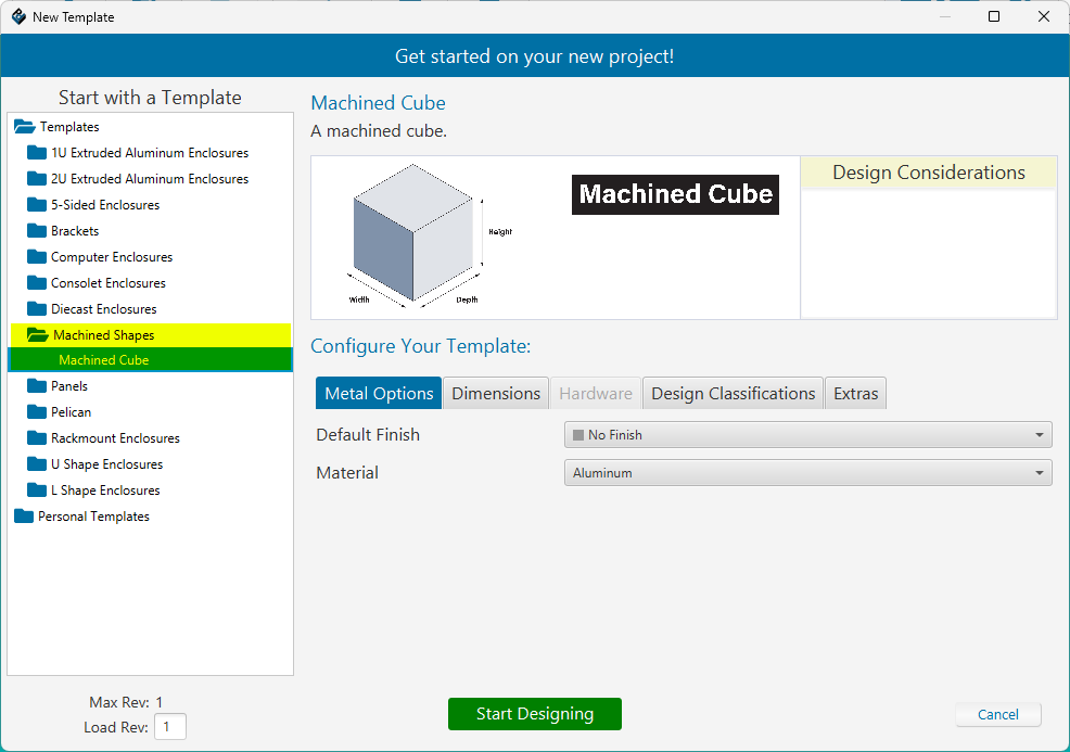
Protocase Designer now includes a Machined Shapes category under templates.
To begin, select the Machined Cube template, you can expect more shapes & templates to come in the future!

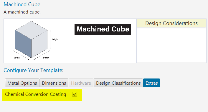
You can customize the finish, material, and dimensions of your part, as well as add Chemical Film Conversion Coating for Aluminum, and Passivation for Stainless Steel. Click on the Extras tab and check the box labelled Chemical Conversion Coating or Passivation.

Once you've selected your desired material, finish and dimensions - click the "Start Designing" button to view your part in 3D and begin making some edits!
Creating Your First Sketch
A Sketch is the starting point of most designs. Think of it like drawing a 2D shape on paper. In CAD software, a sketch is created on a flat surface (like the face of a part or a base plane) and consists of lines, circles, arcs, and other geometric shapes. These 2D outlines are the foundation for creating 3D features like holes, pockets, or solid bodies.
Example: You might sketch a circle to define the base of a cylinder, or a rectangle to later cut a pocket into a part.
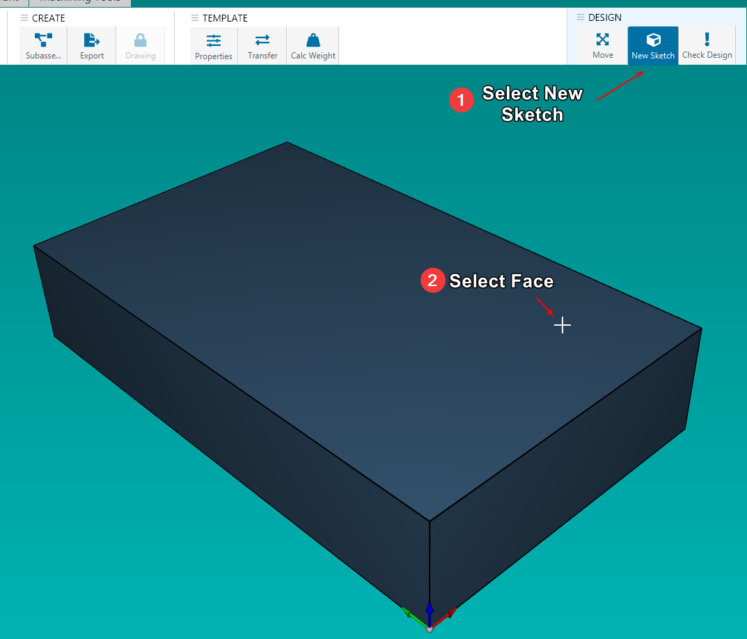
In the 3D view, you need to first select the face which you want to create a sketch on. You can do so by clicking on New Sketch and selecting the face.

Drawing 2D Shapes
After selecting your face to draw your sketch on, it will open up the 2D sketch editor. For a more detailed look at this window, see Face Editor Overview
The following are the different shapes you can draw in your sketch:
- Circle
- Ellipse
- Rectangle
- Line
- Arc
- Custom Path
