Difference between revisions of "Creating fillets"
From Protocase Designer Documentation
| Line 7: | Line 7: | ||
#;[[File:fillet2_NEW.png]] | #;[[File:fillet2_NEW.png]] | ||
#Click the '''Edit''' tool and draw a selection box around the rectangle (which includes the circles). | #Click the '''Edit''' tool and draw a selection box around the rectangle (which includes the circles). | ||
| − | #;[[File: | + | #;[[File:fillet3_NEW.png]] |
#Click the '''Trim''' tool. | #Click the '''Trim''' tool. | ||
#Zoom in on each circle and erase the outer square line segments and the inner circle arcs to create the fillet. | #Zoom in on each circle and erase the outer square line segments and the inner circle arcs to create the fillet. | ||
Revision as of 01:20, 4 August 2017
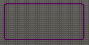
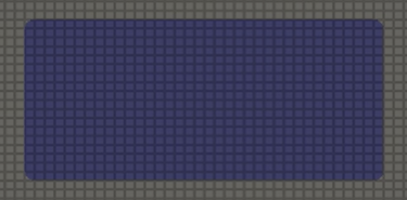
In mechanical engineering, a fillet is a rounding of an interior or exterior corner of a part design. In Designer, you can quickly create fillets using the Trim tool on circles. This tutorial shows how to create a slot with filleted corners.
- To make it easier to make the curves match perfectly, set the grid to the size of the radius you want on the curve.
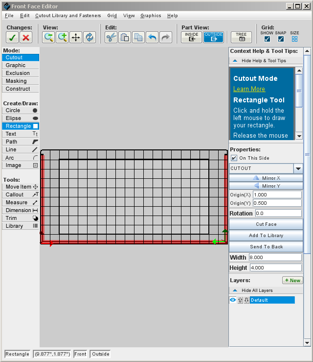
- Draw the rectangle for the slot.
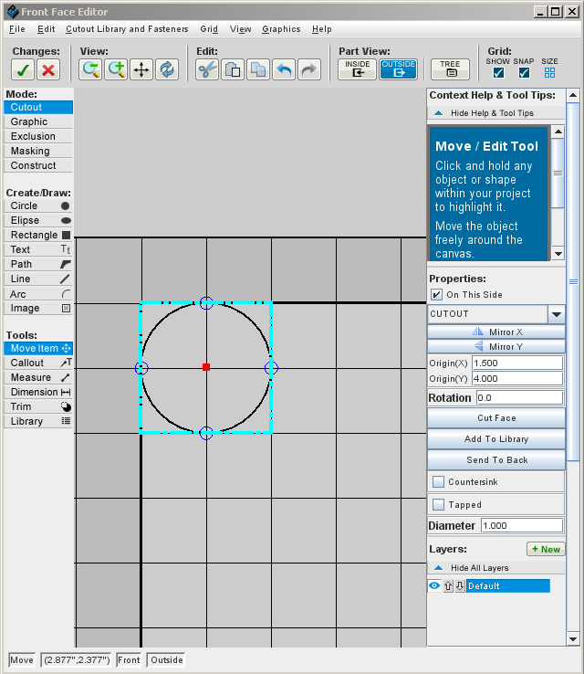
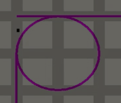
- In each corner, place a circle, using the grid to be precise.
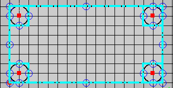
- Click the Edit tool and draw a selection box around the rectangle (which includes the circles).
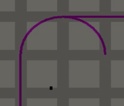
- Click the Trim tool.
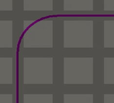
- Zoom in on each circle and erase the outer square line segments and the inner circle arcs to create the fillet.
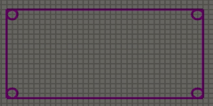
- The filleted corners are complete.
- Press <Esc> or click the Edit tool to complete the trim.
