Difference between revisions of "Creating a custom cutout for a connector"
From Protocase Designer Documentation
(→Method 2: Creating objects in Cutout Editor) |
(→Draw Cutouts) |
||
| Line 5: | Line 5: | ||
There are two methods to create a custom cutout in the Cutout Library. | There are two methods to create a custom cutout in the Cutout Library. | ||
*Method 1—Grouping objects and adding to library | *Method 1—Grouping objects and adding to library | ||
| − | *Method 2—Creating objects directly in Cutout | + | *Method 2—Creating objects directly in the Cutout Editor |
====Method 1: Grouping objects and adding to library==== | ====Method 1: Grouping objects and adding to library==== | ||
Revision as of 14:17, 19 September 2012
Contents
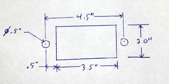
Determine mounting specifications
- Determine the mounting specifications (mounting hole and cutout dimensions) for the connector.
Draw Cutouts
There are two methods to create a custom cutout in the Cutout Library.
- Method 1—Grouping objects and adding to library
- Method 2—Creating objects directly in the Cutout Editor
